


– 18 –
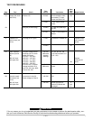
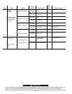
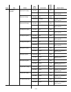
Step
5
6
Next
Test
Step
cont
cont
cont
cont
Test
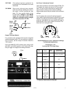
Snubber
Resistors
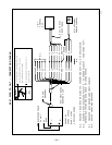
Disconnect leads
401, 402, 403 and
404 from Switch
PC Board
Output diodes
Remove output
load
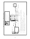
Repair Action
Replace R4
Replace R5
Replace R6
Replace R7
Test individually
Check
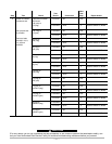
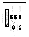
Lead 401 to terminal
12
Lead 402 to terminal
9
Lead 403 to terminal
12
Lead 404 to terminal
9
+ output plug (pos)
to
- output plug (neg)
Test
Result
25 ohms
>30 ohms
<20 ohms
25 ohms
>30 ohms
<20 ohms
25 ohms
>30 ohms
<20 ohms
25 ohms
>30 ohms
<20 ohms
<100 ohms
>200 ohms
Conclusion
OK
R4 open
R4 shorted
OK
R5 open
R5 shorted
OK
R6 open
R6 shorted
OK
R7 open
R7 shorted
Shorted output
diode D1 thru
D12
Output diodes OK
If for any reason you do not understand the test procedures or are unable to perform the tests/repairs safely, con-
tact your local Authorized Field Service Facility for technical troubleshooting assistance before you proceed.
CAUTION