


– 21 –
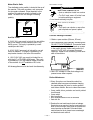
Replacement of Power Modules and Output
Diodes
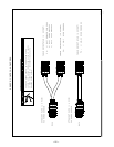
Input rectifier, D13, is a power module. When mount-
ing power modules, the heat sink and module mount-
ing surface should be clean and free of burrs and for-
eign material. Apply heatsink compound (Dow 340) as
a uniform layer ideally .010” thick, to eliminate all air
pockets. This may be verified by mounting and then
removing the module. When removed, the compound
on both surfaces will appear textured as if a vacuum
had created veinlike ridges when the parts were sepa-
rated. If the compound does not have this appear-
ance, apply more heatsink compound and recheck.
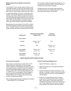
Replacement of output diodes D1 thru D12 is similar.
Clean and brighten mounting surface with fine steel
wool. Compound should be used on surface between
diode and heat sink when mounting individual diodes.
The compound should be applied to the heat sink in a
very thin layer, less than 0.001 in. DO NOT apply on
diode stud and mounting nut threads.
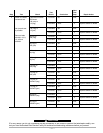
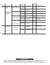
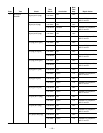
Components must have proper torque applied to
mounting screws and to electrical terminals. Torque
the modules according to the following:
Component to Heat Sink Terminal
Component Torque ±10% Torque ±10%
Switch Board
Module 44 Inch - Lbs.
(1)
N.A.
(5N - m)
Capacitor N.A. 55 Inch - Lbs.
(6.3 N - m)
Input Rectifier 6 Inch - Lbs.
(2)
26 Inch - Lbs.
(M15454-1) (0.7 N - m) 3 (N - m)
Output Diode 25 Inch - Lbs. N.A.
(M15482-2) (3 N - m)
(1)
Retorque after 3 hours to allow for spread of compound.
(2)
Tighten in staggered fashion one quarter turn at a time.
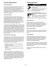
Environment Protection
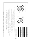
High voltage connections are covered with an RTV
sealant to prevent malfunction in severe environ-
ments. Sealant must be applied to connections which
have been opened or otherwise lost their protection. A
noncorrosive electronic grade sealant such as Dow
Corning 3140, 3145, 738, Columbus Adhesives 0172
or GE RTV-162 is recommended. Sealant may also
be purchased from Lincoln Electric (order E2519
Silicone Rubber RTV Coating). Apply sealant after
machine is repaired and tested.
High voltage areas which require sealant are as listed:
- Input rectifier D13, all 5 terminals.
Printed Circuit Board Replacement
1. Handle PC Boards by edges only.
2. Store PC Boards only in the bags that disperse
static charges.
3. Inspect PC Board for burned conductors or com-
ponents. If damage is visible, inspect the machine
wiring for grounds or shorts to avoid damaging a
new PC Board.
4. If there is no visible damage to the PC Board,
install a new PC Board and see if the problem is
fixed. If the problem is fixed by the new board,
reinstall the old board and see if the problem reoc-
curs. If the problem does not reoccur, check the
wiring harness and plugs for loose connections.