


–
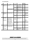
Matched Parts
Certain parts must be replaced in matched sets.
Matched sets are required in the following areas:
Output diodes: D1, D2, D3, D4 and D5
Output diodes: D7, D8, D9, D10 and D11
Capacitor bleeder resistors: R1 and D9
Capacitors: C1 and C2
Capacitors: C1, C2, C14 and C15 (575 VAC only)
Switch PC Board Repairs
If a test indicates that a Switch PC Board is defective,
both Switch PC Boards must be replaced.
Replacement boards must
have completely identical
part numbers. A defective module is likely to damage
other devices in the power circuitry. The defect may
be subtle and not detectable by an ohmmeter mea-
surement. Unknown defective parts may cause newly
replaced parts to fail.
In addition to replacing the Switch PC Boards, replace
C1 and C2 (also C14 and C15 of the 575 VAC V300-
PRO) if the following conditions are met:
1. Machine was operating from 380 VAC or higher
supply when failure occurred.
2. Switch PC Boards have burned areas.
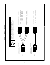
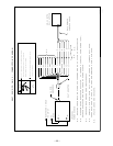
Switch PC Board Replacement Procedure
1. Carefully disconnect the leads at the top of the
Switch PC Board.
2. Remove the four socket head cap screws with a
3/16” hex key wrench.
3. While holding the Switch PC Board, remove the
hex head cap screws from the center area of the
board.
4. Remove the board.
– 20 –
5. Thoroughly clean the heat sink surface.
6. Apply a thin layer (ideally .005-.010”) of Dow 340
Heat Sink Compound to the module mounting sur-
faces of the new Switch PC Board and a thinner
layer (.002”) to the capacitor terminals. Keep the
heat sink compound away from the screw threads
since this compound will affect the torque specifi-
cations.
7. Carefully place the Switch PC Board onto the heat
sink. Be sure the mounting holes are lined up
before making full contact with the heat sink.
8. Caution: The heat sink and the capacitor terminals
are relatively soft material and it is very easy to
cross-thread the mounting screws. Holding the
Switch PC Board, install the 4 socket head cap
screws, finger tight only. Then install the hex head
cap screws into the capacitor, finger tight only.
9. Torque the 4 socket head cap screws to 44 inch-
lbs force (5 N - m). Then torque the capacitor hex
head cap screws to 55 inch-lbs force (6 N - m).
10. Reconnect all the leads to the board.
Before applying input power to the machine, check all
electrical connections. An incorrect connection will result
in machine damage when the power is switched on.
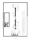
Test After Repair
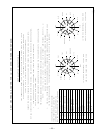
1. Short terminals 14 and 53 of the Protection PC
Board. Connect an ohmmeter, set for X1000
range, to terminals 9 (+) and 12 (-) of the Switch
PC Board. The meter will show the capacitors
charging up. The meter may take a minute or so to
stabilize. The value must not exceed 8600 ohms.
Test both boards. For 575V only units - measure
across each power capacitor, 2 per switch board;
All four readings should be approximately 5,000
ohms.
2. If OK, remove the short and proceed with the
power test.
3. Fuse input supply with 5 amp fuses.
4. Check output open circuit voltages. Do not apply
output load.
5. Connect machine for 460 (V300-PRO), or 575
(V300-PRO, 575V), or 380, 415 or 440 (V300-I)
VAC input.
6. Check output open circuit voltages. Do not apply
output load.
7. Fuse for 20 amps and test under load.
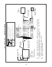
ELECTRIC SHOCK can kill.
• Have an electrician install and service
this equipment.
• Turn the input power off at the fuse
box before working on equipment.
• Do not touch electrically hot parts.
---------------------------------------------------------------------
EXPLODING PARTS can cause
injury.
•
Failed parts can explode or cause other
parts to explode when power is applied.
•
Always wear a face shield and long sleeves when servicing.
----------------------------------------------------------------------------------
WARNING