


The Vantage is shipped with the negative battery cable
disconnected. Before you operate the machine, make sure the
Engine Switch is in the OFF position and attach the disconnected
cable securely to the negative (-) battery terminal.
Remove the insulating cap from the negative battery terminal.
Replace and tighten negative battery cable terminal. NOTE: This
machine is furnished with a wet charged battery; if unused for
several months, the battery may require a booster charge. Be
sure to use the correct polarity when charging the battery.
MUFFLER OUTLET PIPE
Remove the plastic plug covering the muffler outlet tube. Using
the clamp provided secure the outlet pipe to the outlet tube with
the pipe positioned such that it will direct the exhaust in the
desired position.
SPARK ARRESTOR
Some federal, state or local laws may require that petrol or diesel
engines be equipped with exhaust spark arrestors when they are
operated in certain locations where unarrested sparks may
present a fire hazard. The standard muffler included with this
welder does not qualify as a spark arrestor. When required by
local regulations, a suitable spark arrestor, must be installed and
properly maintained.
An incorrect arrestor may lead to damage to the engine or
adversely affect performance.
--------------------------------------------------------------------------------------
WELDING TERMINALS
The Vantage is equipped with a toggle switch for selecting "hot"
welding terminals when in the "WELD TERMINALS ON" position
or "cold" welding terminals when in the "REMOTELY
CONTROLLED" position.
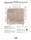
WELDING OUTPUT CABLES
With the engine off, route the electrode and work cables thru the
strain relief bracket provided on the front of the base and connect
to the terminals provided. These connections should be checked
periodically and tightened if necessary.
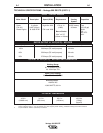
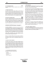
Listed in Table A.1 are copper cable sizes recommended for the
rated current and duty cycle. Lengths stipulated are the distance
from the welder to work and back to the welder again. Cable sizes
are increased for greater lengths primarily for the purpose of
minimizing cable voltage drop.
Table A.1 Combined Length of Electrode and Work Cables.
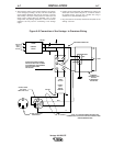
MACHINE GROUNDING
Because this portable engine driven welder creates its own
power, it is not necessary to connect its frame to an earth ground,
unless the machine is connected to premises wiring (home, shop,
etc.).
To prevent dangerous electric shock, other equipment powered
by this engine driven welder must:
a) be grounded to the frame of the welder using a
grounding type plug,
or
b) be double insulated.
When this welder is mounted on a truck or trailer, its frame must
be securely connected to the metal frame of the vehicle. When
this engine driven welder is connected to premises wiring such as
that in a home or shop, its frame must be connected to the system
earth ground. See further connection instructions in the section
entitled “Standby Power Connections” as well as
the article on grounding in the latest National Electrical Code and
the local codes.
In general, if the machine is to be grounded, it should be
connected with a #8 or larger copper wire to a solid earth ground
such as a metal ground stake going into the ground for at least 10
Feet or to the metal framework of a building which has been
effectively grounded. The National Electric Code lists a number of
alternate means of grounding electrical equipment. A machine
grounding stud marked with the symbol is provided on the
front of the welder.
A-5 INSTALLATION A-5
Vantage 500 DEUTZ
CAUTION
AMPS Up to 150ft 150-200ft 200-250ft
@100%
Duty Cycle
500 3/0 AWG 3/0 AWG 4/0 AWG
TOTAL COMBINED LENGTH OF
ELECTRODE AND WORK CABLES