


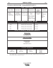

CONNECTION OF LINCOLN ELECTRIC
WIRE FEEDERS
Shut off welder before making any electrical connections.
-------------------------------------------------------------------------------------
CONNECTION OF LN-7, LN-8 OR LN-742 TO THE
VANTAGE
• Shut the welder off.
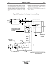
• Connect the LN-7, LN-8 or LN-742 per instructions on the
appropriate connection diagram in the DIAGRAMS section.
• Set the “WIRE FEEDER VOLTMETER” switch to either “+” or “-
” as required by the electrode being used.
• Set the “SELECTOR” switch to the “CV-WIRE” position.
• Adjust the “ARC CONTROL” knob to desired Crispness. SOFT
for MIG and CRISP for INNERSHIELD.
• Set the “WELDING TERMINALS” switch to the “REMOTELY
CONTROLLED” position.
CONNECTION OF LN-15 TO THE VANTAGE
These connections instructions apply to both the LN-15 Across-
The-Arc and Control Cable models. The LN-15 has an internal
contactor and the electrode is not energized until the gun trigger
is closed. When the gun trigger is closed the wire will begin to
feed and the welding process is started.
• Shut the welder off.
• For electrode Positive, connect the electrode cable to the "+"
terminal of the welder and work cable to the "-" terminal of the
welder. For electrode Negative, connect the electrode cable "-"
terminal of the welder and work cable to the "+" terminal of the
welder.
• Across-The-Arc Model:
Attach the single lead from the front of the LN-15 to work
using the spring clip at the end of the lead. This is a control
lead to supply current to the wire feeder motor; it does not
carry welding current.
Control Cable Model:
Connect Control Cable between Engine Welder and Feeder.
• Set the MODE switch to the "CV-WIRE " position.
• Across-The-Arc Model:
Set the "WELD TERMINALS" switch to "WELD TERMINALS
ON"
Control Cable Model:
Set the "WELD TERMINALS" switch to "REMOTELY
CONTROLLED"
• Set the "WIRE FEEDER VOLTMETER" switch to either "+" or
"-" as required by the electrode polarity being used.
• Set the "ARC CONTROL" knob to "0" initially and adjust to suit.
CONNECTION OF AN LN-23P WIRE FEEDER TO
THE VANTAGE
• Shut the welder off.
• Connect the LN-23P per instructions on the appropriate
connection diagram in the DIAGRAMS section. (NOTE): When
connecting an LN-23P to the Vantage , a K350-1 adapter kit
must be used.
• Set the “WIRE FEEDER VOLTMETER” switch to “-”.
• Set the “SELECTOR” switch to “CV-WIRE” position.
• Set the “WELDING TERMINALS” switch to “REMOTELY
CONTROLLED”.
• Set the ARC CONTROL to desired crispness.
• If you are using an LN-23P with the K350-1 adapter kit, the
electrode is not energized until the gun trigger is closed.
A-8 INSTALLATION A-8
Vantage 500 DEUTZ
WARNING