


REMOTE CONTROL
OUTPUT
The Vantage is equipped with a 6-pin and a 14-pin connector. The
6-pin connector is for connecting the K857 or K857-1 Remote
Control or for TIG welding, the K870 foot Amptrol or the K936-2
hand Amptrol. When in the CC-STICK, DOWNHILL PIPE, or CV-
WIRE modes and when a remote control is connected to the 6-
pin Connector, the auto-sensing circuit automatically switches the
OUTPUT control from control at the welder to remote control.
When in TOUCH START TIG mode and when a Amptrol is
connected to the 6-Pin Connector, the OUTPUT dial is used to set
the maximum current range of the CURRENT CONTROL of the
Amptrol.
The 14-pin connector is used to directly connect a wire feeder
control cable. In the CV-WIRE mode, when the control cable is
connected to the 14-pin connector, the auto-sensing circuit
automatically makes the Output Control inactive and the wire
feeder voltage control active.
NOTE: When a wire feeder with a built in welding voltage control
is connected to the 14-pin connector, do not connect anything to
AUXILIARY POWER RECEPTACLES
The auxiliary power capacity of the Vantage is 12,000 watts of 60
Hz, single phase power. The auxiliary power capacity rating in
watts is equivalent to volt-amperes at unity power factor. The
maximum permissible current of the 240 VAC output is 50 A. The
240 VAC output can be split to provide two separate 120 VAC
outputs with a maximum permissible current of 50 A per output to
two separate 120 VAC branch circuits. The output voltage is
within ± 10% at all loads up to rated capacity.
The Vantage has two 20 Amp-120VAC (5-20R) GFCI duplex
receptacles and one 50 Amp-120/240 VAC (14-50R) receptacle.
The 120/240 VAC receptacle can be split for single phase 120
VAC operation. The auxiliary power receptacles should only be
used with three wire grounded type plugs or approved double
insulated tools with two wire plugs. The current rating of any plug
used with the system must be at least equal to the current
capacity of the associated receptacle.
NOTE: The two 120V GFCI receptacles and the two 120 volt
circuits of the 120/240V receptacle are connected to different
phases and can not be paralleled.
STANDBY POWER CONNECTIONS
The Vantage is suitable for temporary, standby or emergency
power using the engine manufacturer’s recommended
maintenance schedule.
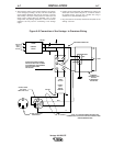
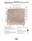
The Vantage can be permanently installed as a standby power
unit for 240 volt-3 wire, 50 amp service. Connections must be
made by a licensed electrician who can determine how the
120/240 VAC (60Hz) power can be adapted to the particular
installation and comply with all applicable electrical codes. The
following information can be used as a guide by the electrician for
most applications. Refer to the connection diagram shown in
Figure A.2.
1. Install the double-pole, double-throw switch between the power
company meter and the premises disconnect.
Switch rating must be the same or greater than the customer’s
premises disconnect and service over current protection.
A-6 INSTALLATION A-6
Vantage 500 DEUTZ