


14. WIRE FEEDER VOLTMETER SWITCH:
Matches the polarity of the wire feeder voltmeter to the polarity of
the electrode.
15. 6 - PIN CONNECTOR
For attaching optional remote control equipment. Includes auto-
sensing remote control circuit.
16. 14 - PIN CONNECTOR
For attaching wire feeder control cables. Includes contactor
closure circuit, auto-sensing remote control circuit, and 120VAC
and 42VAC power.
NOTE: When a wire feeder with a built in welding voltage control
is connected to the 14-pin connector, do not connect anything to
the 6-pin connector.
17. WELD OUTPUT TERMINALS + AND -
These 1/2 - 13 studs with flange nuts provide welding connection
points for the electrode and work cables. For positive polarity
welding the electrode cable connects to the “+” terminal and the
work cable connects to this “-” terminal. For negative polarity
welding the work cable connects to the “+” terminal and the
electrode cable connects to this “-” terminal.
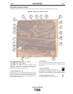
AUXILIARY POWER CONTROLS
(Items 18-21)
18. 120/240 VAC RECEPTACLE
This is a 120/240VAC (14-50R) receptacle that provides 240VAC
or can be split for 120VAC single phase auxiliary power. This
receptacle has a 50 amp rating. Refer to the AUXILIARY POWER
RECEPTACLES section in the installation chapter for further
information about this receptacle. Also refer to the AUXILIARY
POWER OPERATION section later in this chapter.
19. CIRCUIT BREAKERS
These circuit breakers provide separate overload current
protection for each 120V circuit at the 240V receptacle, each
120V receptacle, the 120VAC in the 14-Pin connector, the 42VAC
in the 14-Pin connector and battery circuit overload protection.
20. 120VAC GFCI RECEPTACLES
These two 120VAC (5-20R) receptacles with ground fault circuit
interruption protection provide 120VAC for auxiliary power. Each
receptacle has a 20 amp total rating. They are designed to protect
the user from the hazards of ground faults. When the GFCI has
tripped there will be no voltage available from the receptacle. If
the GFCI has tripped, any device plugged into the GFCI
receptacle should be unplugged and the reason for tripping the
GFCI should be determined. If the device is found to be damaged
or defective, it should be repaired or replaced before any further
use. The GFCI should be checked for proper operation prior to
each use by pressing the test button. The GFCI can be reset by
pushing the reset button. Refer to the AUXILIARY POWER
RECEPTACLES section in the installation chapter for further
information about these receptacles. Also refer to the AUXILIARY
POWER OPERATION section later in this chapter.
21. GROUND STUD
Provides a connection point for connecting the machine case to
earth ground. Refer to “MACHINE GROUNDING” in the
Installation chapter for proper machine grounding information.
ENGINE OPERATION
STARTING THE ENGINE
1. Open the engine compartment door and check that the fuel
shutoff valve located to the left of the fuel filter housing is in the
open position (lever to be in line with the hose).
2. Check for proper oil level. Close engine compartment door.
3. Remove all plugs connected to the AC power receptacles.
4. Set the RUN/STOP switch to “RUN”. Observe that the engine
protection and battery charging lights are on. After 10 seconds,
the engine protection light will turn off.
5. Within 30 seconds, press and hold the engine START button
until the engine starts.
6. Release the engine START button when the engine starts.
7. Check that the engine protection and battery charging lights
are off. The engine protection light is on after starting, the
engine will shutdown in a few seconds. Investigate any
indicated problem.
8. Allow the engine to warm up for several minutes before
applying a load. Allow a longer warm up time in cold weather.
COLD WEATHER STARTING
With a fully charged battery and the proper weight oil, the engine
should start satisfactorily even down to about 0°F. If the engine
must be frequently started below 10°F, it may be desirable to
install the optional ether start kit (K825-1). Installation and
operating instructions are included in the kit.
STOPPING THE ENGINE
1. Switch the RUN/STOP switch to “STOP”. This turns off the
voltage supplied to the shutdown solenoid. A backup shutdown
can be accomplished by shutting off the fuel valve located on
the fuel line.
B-4 OPERATION B-4
Vantage 500 DEUTZ