


Vantage 500 DEUTZ
F-14 DIAGRAMS F-14
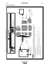
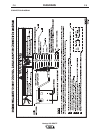
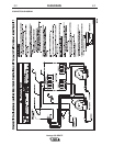
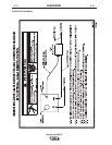
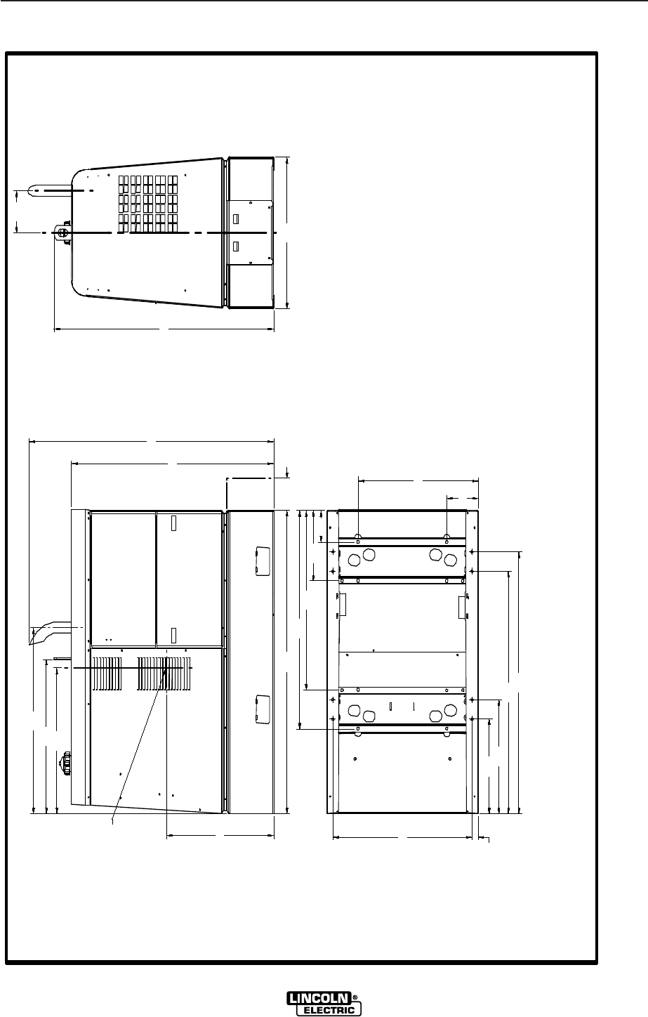
DIMENSION PRINT
TRAILER MOUNTING HOLE LOCATIONS.
*
M18962-1
A
28.99
1.26
19.63
6.53
24.97
6.55
23.69
50.38
54.44
14.63
37.30
45.38
63.10 6.56
42.00
48.64
23.38
31.13
32.08
49.05
31.50
45.67
10.22
*
*
*
*
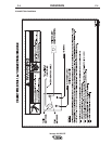
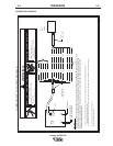
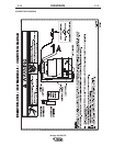
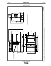
BOTTOM VIEW OF WELDER BA
CENTER OF GRAVITY WITH OIL
IN ENGINE AND FULL FUEL TANK.
NOTE: This diagram is for reference only. It may not be accurate for all machines covered by this manual. The specific diagram for a particular code is pasted inside the machine on one of the enclosure
panels. If the diagram is illegible, write to the Service Department for a replacement. Give the equipment code number.