


%*+##+ &%
'&.)S$* %#. ))
*+0'),+ &%
#&+ &%
• The Power Feed™ 10M Single Wire Feeder has an
IP21 rating, suitable for indoor use.
• The Power Feed™ 10M Single Wire Feeder should
be operated in a substantially upright position.
• Do not submerge the Power Feed™ 10M Single
Wire Feeder.
• The Power Feed™ 10M Single Wire Feeder is not
suitable for stacking.
Locate the Power Feed™ 10M Single Wire Feeder
away from radio controlled machinery. The normal
operation of the Power Feed™ 10M Single Wire
Feeder may adversely affect the operation of RF con-
trolled equipment, which may result in bodily injury or
damage to the equipment.
#+) *&"53@=;>>
R&@>KCG3>;8;76B7DEA@@7>E:AG>6
B7D8AD?F:;E;@EF3>>3F;A@
R+GD@A88F:7;@BGFBAI7DFAF:7
BAI7DEAGD573FF:76;E5A@@75F
EI;F5:AD8GE74AJ478AD7IAD=;@9
A@F:;E7CG;B?7@F+GD@A88F:7
;@BGFBAI7DFA3@KAF:7D7CG;B?7@F
5A@@75F76FAF:7I7>6;@9EKEF7?3F
F:76;E5A@@75FEI;F5:AD8GE74AJ
478AD7IAD=;@9A@F:;E7CG;B?7@F
RA@AFFAG5:7>75FD;53>>K:AFB3DFE
----------------------------------------------------------------------------------------
,)
$&,%+ %
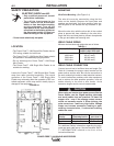
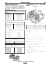
.;D7D;H7$AG@F;@9(See Figure A.1)
The wire drive may be mounted by using the four
holes on the bottom. Because the feed plate and
gearbox are electrically "hot" when welding, make cer-
tain the parts do not contact the any structure or per-
son.
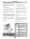
Mount the wire drive with the drive rolls in the vertical
plane to prevent dirt from collecting in the wire drive.
Angle the drive and feed plate to prevent sharp bends
in the gun and cable and incoming wire.
.##* 1 %
Minimum work and electrode cables sizes are as follows:
+#
GDD7@FGFKK5>7
$ % $,$&'')
.&)"#* 1.
Up To-100 Ft. Length (30 m)
400 Amps 2/0 (67 mm2)
500 Amps 3/0 (85 mm2)
600 Amps 3/0 (85 mm2)
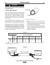
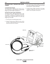
.##&%%+ &%
Connect a work lead of sufficient size and length (Per
Table A.1) between the proper output terminal on the
power source and the work. Be sure the connection to
the work makes tight metal-to-metal electrical contact.
To avoid interference problems with other equipment
and to achieve the best possible operation, route all
cables directly to the work or wire feeder. Avoid
excessive lengths and do not coil excess cable.
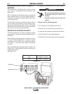
.:7@GE;@93@;@H7DF7DFKB7BAI7DEAGD57>;=7F:7
'AI7D.3H7EGE7F:7>3D97EFI7>6;@97>75FDA67
3@6IAD=534>7EF:3F3D7BD35F;53>F>73EF
5ABB7DI;D77H7@;8F:73H7D397AGFBGF5GDD7@F
IAG>6@AF@AD?3>>KD7CG;D7;F.:7@BG>E;@9F:7
BG>E75GDD7@F53@D735:H7DK:;9:>7H7>E-A>F397
6DABE53@475A?77J57EE;H7>736;@9FABAAD
I7>6;@95:3D35F7D;EF;5E;8G@67DE;L76I7>6;@9
534>7E3D7GE76
------------------------------------------------------------------------
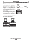
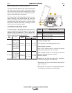
AD>75FDA67 A@@75FF:7 A@@75FF:7
'A>3D;FK >75FDA67>736FA IAD=>736FA
Positive Positive Stud Negative
Negative Negative Stud Positive Stud
For additional Safety information regarding the elec-
trode and work cable set-up, See the standard "SAFE-
TY INFORMATION" located in the front of the
Instruction Manuals.