


H;
H;
+#&&%+%+*
Page
@EF3>>3F;A@*75F;A@
Technical Specifications................................................................................................A-1
Safety Precautions ...............................................................................................................A-2
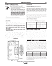
Location.........................................................................................................................A-2
Mounting .......................................................................................................................A-2
Safety Precautions ...............................................................................................................A-2
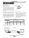
Weld Cable Sizing.........................................................................................................A-2
Weld Cable Connection ................................................................................................A-2
Coaxial Weld Cables.....................................................................................................A-3
Weld Cable Sizes..........................................................................................................A-3
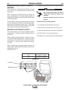
Changing Electrode Polarity.................................................................................................A-4
Negative Electrode Polarity...........................................................................................A-4
Cables .................................................................................................................................A-5
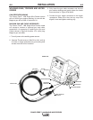
Digital Control Cable ....................................................................................................A-5
Welding gun/Wire Feeder Trigger Connector ...............................................................A-5
Wire Drive Systems..............................................................................................................A-6
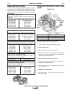
Changing Drive Rolls and Wire Guides.........................................................................A-6
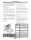
Drive Roll Pressure Setting...........................................................................................A-7
Changing The Gun Receiver Bushing...........................................................................A-7
Welding Gun Torch and Accessories............................................................................A-8
Wire Feed Shut Down Circuit........................................................................................A-9
Changing the Gear Ratio ..............................................................................................A-9
Wire Reel Loading.......................................................................................A-10 thru A-12
Shielding Gas Connection..................................................................................................A-13
Examples of Connecting an Arclink Power Wave System .................................................A-14
________________________________________________________________________________
&B7D3F;A@*75F;A@
Safety Precautions ...............................................................................................................B-1
Graphic Symbols .................................................................................................................B-1
Definitions of Welding Modes...............................................................................................B-1
Product Description..............................................................................................................B-2
Bench Model Features..................................................................................................B-3
Basic Power Feed™ 10M Single Wire Feeder Welding System Configuration ............B-3
Front Panel Controls and Connections ................................................................................B-4
1. Status LED................................................................................................................B-5
2. Digital Meters and Output Encoder Knobs................................................................B-5
A. Wire Feed Speed/Ammeter display and output Knob...........................................B-5
B. Volts/Trim display and Output Knob .....................................................................B-6
Synergic CV Voltage Display ....................................................................................B-6
Overview: ..................................................................................................................B-7
3. Mode Select Panel 4 (MSP4)....................................................................................B-7
Layout-Controls.........................................................................................................B-7
Layout-Digital Displays..............................................................................................B-7
Power-up Sequence..................................................................................................B-8
Changing Weld Modes..............................................................................................B-8
Changing Arc Wave Control......................................................................................B-8
Changing Weld Sequence Behavior .........................................................................B-8
Infrared (IR) Control ..................................................................................................B-8
Lockout/security ........................................................................................................B-8
Limit Setting ..............................................................................................................B-9
Machine Setup/user preferences ..............................................................................B-9
Accessing the Machine Setup Menu.........................................................................B-9
Setup Features Menu..............................................................................B-10 thru B-17
4. Cold Feed / Gas Purge Switch................................................................................B-18
5. 2-Step/4- 4 Step Trigger Switch Operations...........................................B-18, thru B-20
Process Set-Up and Operation ...............................................................................B-21
Steel and Stainless Synergic GMAW-P (Pulsed MIG) Welding..............................B-22
Arc Control ..............................................................................................................B-22