


'*I;F5:'AE;F;A@
ON
OFF
'A>3D;FK
(negative) - polarity
(positive) + polarity
,)
% %#+)&'&#) +0
*++ %
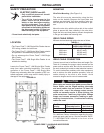
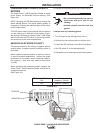
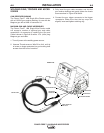
The Power Feed™ 10M Single Wire Feeder is preset
at the factory for Electrode Positive welding. (See
Figure A.3)
NOTE: Changing this DIP Switch does not change the
actual welding polarity. The actual welding polarity is
changed by reversing the welding cables at the power
source output studs.
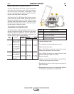
This DIP Switch setting must coincide with the polarity
you are setting up to weld with for the feeder to oper-
ate correctly. Operating the Power Feed™ 10M Single
Wire Feeder with the DIP switch in the wrong position
will cause very erratic weld characteristics.
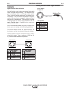
%+ -#+)&'&#) +0
This options allows for the setting of negative polarity
sensing when a negative polarity welding process is
performed.
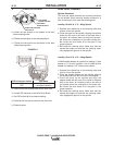
When negative electrode polarity is required, such as
in some Innershield applications, reverse the output
connections at the power source (electrode cable to
the negative (-) stud, and work cable to the positive
(+) stud).
When operating with electrode polarity negative the
Power Feed™ 10M Single Wire Feeder must be set to
recognize this set-up.
(See Figure A.3)
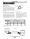
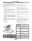
%*+##+ &%
'&.)S$* %#. ))
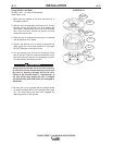
To change the electrode polarity DIP Switch setting:
7,+,11,2!&#)#!1/'!))6)'3#-/10,/
#)#!1/,"#04'1&6,2/0('+,/4#1
!),1&'+%
7+02)1#6,2/0#)$$/,*1,/(+"
%/,2+"
7)4604#/"/6'+02)1'+%%),3#0
------------------------------------------------------------------------
1. Turn off power at the welding power source.
2. Remove the rear access panel on the wire drive.
3. Locate the DIP switches on the Wire Drive Board.
4. Set DIP switch #7 to the desired polarity.
5. Reinstall the rear access panel and restore power.
.)% %
NEGATIVE
POSITIVE