


+)&,#*&&+ %
'&.)S$* %#. ))
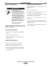
Observe all Safety Guidelines detailed throughout this manual
If for any reason you do not understand the test procedures or are unable to perform the tests/repairs safely, contact your
#A53>#;@5A>@GF:AD;L76;7>6*7DH;5735;>;FK for technical troubleshooting assistance before you proceed.
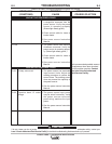
,+ &%
')&#$*
*0$'+&$*
'&** #
,*
)&$$%
&,)*&+ &%
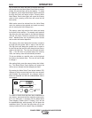
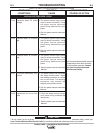
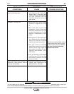
If all recommended possible areas of
misadjustment have been checked
and the problem persists, A@F35F
KAGD>A53>#;@5A>@GF:AD;L76
;7>6*7DH;5735;>;FK
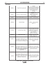
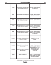
Err 33 Capacitor bank "B" under
voltage.
Err 34 Capacitor bank "A" overvolt-
age.
Err 35 Capacitor bank "B" overvolt-
age.
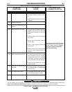
Err 41 Long term secondary over-
current.
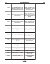
Err 43 Capacitors are out of bal-
ance
1. The power source input power
may be wired incorrectly. Verify
the power source reconnect
panel wiring matches the input
power.
2. See the power source Instruction
Manual.
1. The power source input power
may be wired incorrectly. Verify
the power source reconnect
panel wiring matches the input
power.
2. See the power source Instruction
Manual.
1. The power source input power
may be wired incorrectly. Verify
the power source reconnect
panel wiring matches the input
power.
2. See the power source Instruction
Manual.
1. The power source has exceeded
the output current limits. Adjust
the welding procedure to reduce
the current draw. The welding
procedure may exceed the
capacity of the power source.
2. See the power source Instruction
Manual.
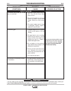
1. Verify the power source recon-
nect panel wiring matches the
input power.
2. See the power source Instruction
Manual.
)# %"*0*+$))&)&*