


$)*""*%$
&%-(R#+"-((
$*,"*(%&%"(*/
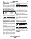
When negative electrode polarity is required, such as
in some Innershield applications, reverse the output
connections at the power source (electrode cable to
the negative (-) stud, and work cable to the positive
(+) stud).
"*(%)$)&%"(*/
This options allows for the setting of negative polarity
sensing when a negative polarity welding process is
performed.
When negative electrode polarity is required, such as
in some Innershield applications, reverse the output
connections at the power source (electrode cable to
the negative (-) stud, and work cable to the positive
(+) stud).
When operating with electrode polarity negative the
Wire Feeder must be set to recognize this option.
*B)8GG;8?86GEB78)8AF8&B?4E<GL)J<G6;
"*()%!64A><??
Q*HEAG;8<ACHGCBJ8E%4GG;87<F
6BAA86GFJ<G6;589BE8JBE><A:BA
G;<F8DH<C@8AG
QBABGGBH6;8?86GE<64??L;BGC4EGF
-;8A6;4A:<A:G;88?86GEB78CB?4E<GLG;8J8?7
645?8F@HFG586;4A:874GG;8CBJ8EFBHE68
FGH7F4A7G;8&FJ<G6;<AF<78G;8&BJ8E887
#H4?@HFG58CEBC8E?LF8G%C8E4G<BAJ<G;G;8
&FJ<G6;<AG;8JEBA:CBF<G<BAJ<??64HF88EE4G<6
4E6C8E9BE@4A68
------------------------------------------------------------------------
%+*&+*")%$$*%$)
$"#**%$)
Connect a work lead of sufficient size and length (Per
Table A.1) between the proper output terminal on the
power source and the work. Be sure the connection to
the work makes tight metal-to-metal electrical contact.
To avoid interference problems with other equipment
and to achieve the best possible operation, route all
cables directly to the work or wire feeder. Avoid
excessive lengths and do not coil excess cable.
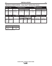
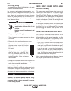
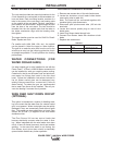
Minimum work and electrode cables sizes are as follows:
*"
HEE8AGHGLL6?8
#$#+#%&&(
-%(!")0-
Up To-100 Ft. Length (30 m)
400 Amps 2/0 (67 mm2)
500 Amps 3/0 (85 mm2)
600 Amps 3/0 (85 mm2)
NOTE: K1796 coaxial welding cable is recommended
to reduce the cable inductance in long distance Pulse
applications up to 300 amps.
-;8AHF<A:4A<AI8EG8EGLC8CBJ8EFBHE68?<>8G;8
&BJ8E-4I8FHF8G;8?4E:8FGJ8?7<A:8?86GEB78
4A7JBE>645?8FG;4G4E8CE46G<64?G?84FG
6BCC8EJ<E88I8A<9G;84I8E4:8BHGCHG6HEE8AG
JBH?7ABGABE@4??LE8DH<E8<G-;8ACH?F<A:G;8
CH?F86HEE8AG64AE846;I8EL;<:;?8I8?F,B?G4:8
7EBCF64A586B@88K68FF<I8?847<A:GBCBBE
J8?7<A:6;4E46G8E<FG<6F<9HA78EF<M87J8?7<A:
645?8F4E8HF87
------------------------------------------------------------------------
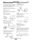
Output connections on some Power Waves® are
made via 1/2-13 threaded output studs located
beneath the spring loaded output cover at the bottom
of the case front.
Most welding applications run with the electrode being
positive (+). For those applications, connect the elec-
trode cable between the wire feeder and the positive
(+) output stud on the power source (located beneath
the spring loaded output cover near the bottom of the
case front). Connect the other end of the electrode
cable to the wire drive feed plate. The electrode cable
lug must be against the feed plate. Be sure the con-
nection to the feed plate makes tight metal-to-metal
electrical contact. The electrode cable should be sized
according to the specifications given in the work cable
connections section. Connect a work lead from the
negative (-) power source output stud to the work
piece. The work piece connection must be firm and
secure, especially if pulse welding is planned.
For additional Safety information regarding the elec-
trode and work cable set-up, See the standard "SAFE-
TY INFORMATION" located in the front of the
Instruction Manuals.
K68FF<I8IB?G4:87EBCF64HF875LCBBEJBE>
C<8686BAA86G<BAFB9G8AE8FH?G<AHAF4G<F946GBEL
J8?7<A:C8E9BE@4A68
------------------------------------------------------------------------
-($$