


$)*""*%$
&%-(R#+"-((
&(%+( *%$)*"" (,
(%"")$-(+)
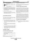
E<I8(B??!<GAFG4??4G<BA!&12
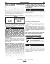
• Turn OFF Welding Power Source.
• Pull open Pressure Door to expose rolls and wire
guides.
• Remove Outer Wire Guide by turning knurled thumb
screws counter-clock-wise to unscrew them from
Feedplate.
• Remove drive rolls, if any are installed, by pulling
straight off shaft. Remove inner guide.
+$$ "))#")
-*)*$(%$$*%$
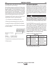
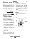
The Power Feed™ 10 Dual Wire Feeder is equipped
with a factory installed K1500-2 gun connection Kit.
This kit is for guns having a Tweco™ #2-#4 connec-
tor. The Power Feed™ 10 Dual Wire Feederl has
been designed to make connecting a variety of guns
easy and inexpensive with the K1500 series of gun
connection kits. Gun trigger and dual procedure lead
connections connect to the single 5 pin receptacle on
the front of the feed head box. See “Gun Adapters” in
ACCESSORIES section.
+$$ "))#")
-* )*#*™ %$$*%$
<A6?H7<A:G;8#4:AH@-4G8EBB?87:HA
A K489-9 adapter will install directly into the wire drive
feedplate, to provide for use of guns with Fast-Mate™
or European style gun connections. This K489-9 will
handle both standard Fast-Mate™and Dual Schedule
Fast-Mate™ guns.
Another way to connect a gun with a Fast-Mate™ or
European style gun connector to the Power Feed™
10 Dual Wire Feeder, is to use the K489-10 Fast-
Mate™ adapter kit. Installation of this adapter also
requires a K1500-1 gun connector. See “Gun
Adapters” in ACCESSORIES section.
#4:AH@HAF
The easiest and least expensive way to use Magnum
200/300/400 guns with the Power Feed™ 10 Dual
Wire Feeder is to order them with the K466-10 con-
nector kit, or to buy a completely assembled Magnum
gun having the K466-10 connector (such as the K497-
21 dedicated Magnum 400).
-($$
%5F8EI84??477<G<BA4?)498GLH<78?<A8F78G4<?87
G;EBH:;BHGG;<F@4AH4?
"*()%!64A><??
Q BABGGBH6;8?86GE<64??L?<I8C4EGFFH6;
4FBHGCHGG8E@<A4?FBE<AG8EA4?J<E<A:
Q
-;8A9887<A:J<G;BHG&BJ8E887H4?UB?7
887V984GHE88?86GEB784A77E<I8@86;4A<F@
4E8U;BGVGBJBE>4A7:EBHA74A76BH?7E8@4<A
8A8E:<M87F8I8E4?F86BA7F49G8EG;8:HAGE<::8E
<FE8?84F87
Q *HEA%<ACHGCBJ8E4GJ8?7<A:CBJ8E
FBHE68589BE8<AFG4??4G<BABE6;4A:<A:7E<I8
EB??4A7BE:H<78GH58F
Q -8?7<A:CBJ8EFBHE68@HFG586BAA86G87
GBFLFG8@:EBHA7C8EG;8$4G<BA4??86GE<64?
B78BE4AL4CC?<645?8?B64?6B78F
• %A?LDH4?<9<87C8EFBAA8?F;BH?7
C8E9BE@G;<F<AFG4??4G<BA
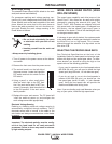
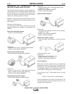
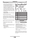
• Insert inner Wire Guide, groove side out, over the
two locating pins in the feedplate.
• Install each drive roll by pushing over shaft until it
butts up against locating shoulder on the drive roll
shaft. (Do Not exceed maximum wire size rating of
the wire drive).
• Install Outer Wire Guide by sliding over locating pins
and tightening in place.
• Engage upper drive rolls if they are in the “open”
position and close Pressure Door.
TO SET DRIVE ROLL PRESSURE, see “Drive Roll
Pressure Setting” in OPERATION.
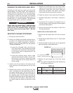
-((,(%""!*)
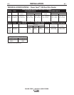
NOTE: The maximum rated solid and cored wire sizes
and selected drive ratios are shown on the
SPECIFICATIONS in the front of this section.
The electrode sizes that can be fed with each roll and
guide tube are stenciled on each part. Check the kit
for proper components. Kit specifications can be found
in the ACCESSORIES section.