


$)*""*%$
&%-(R#+"-((
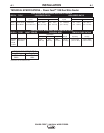
#4:AH@HAF
The easiest and least expensive way to use the
Magnum 550 guns with Power Feed™ 10 Dual wire
feeders is to order the gun with the K613-7 connector
kit, and install a K1500-3 gun connection kit to the
wire feeder.
"<A6B?AAA8EF;<8?74A7)H5E6HAF
All of these guns can be connected to the Power
Feed™ 10 Dual Wire Feeder by using the K1500-1
Adapter Kit.
"<A6B?AH@8KGE46G<BAHAF
The K556 (250XA) and K566 (400XA) guns require
that a K489-10 Fast-Mate™ adapter kit be installed.
Installation of this adapter also requires a K1500-1
gun connector kit.
The K206, K289, and K309 require only the installa-
tion of a K1500-1 connector in the Power Feed wire
feeder.
$BA"<A6B?AHAF
Most competitive guns can be connected to the Power
Feed™ 10 Dual Wire Feeder by using one of the
K1500 series adapter kits, See “Gun Adapters” in
ACCESSORIES section.
$(" +$ %$$*%$
+"$)
The instructions supplied with the gun and K1500
series gun adapter should be followed when installing
and configuring a gun. What follows are some gener-
al guidelines that are not intended to cover all guns.
a. Check that the drive rolls and guide tubes are
proper for the electrode size and type being used.
If not, change them.
b. Lay the cable out straight. Insert the connector
on the welding conductor cable into the brass
conductor block on the front of the wire drive
head. Make sure it is all the way in and tighten
the hand clamp. Keep this connection clean and
bright. Connect the trigger control cable polarized
plug into the mating 5 cavity receptacle on the
front of the wire drive unit.
#-)"$)
$%*Gas supply pressure must be regulated to a
maximum of 80 psi(5.5 bar).
Customer must provide a cylinder of shielding gas, a
pressure regulator, a flow control valve, and a hose
from the flow valve to the gas inlet fitting of the wire
drive unit.
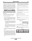
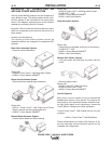
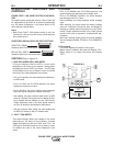
Connect a supply hose from the gas cylinder flow
valve outlet to the 5/8-18 female inert gas fitting on the
back panel of the wire drive or, if used, on the inlet of
the Gas Guard regulator. (See Below).
4FH4E7(8:H?4GBEThe Gas Guard Regulator is
an optional accessory (K659-1) on these models.
Install the 5/8-18 male outlet of the regulator to the
5/8-18 female gas inlet on the back panel of the wire
drive. Secure fitting with flow adjuster key at top.
Attach gas supply to 5/8-18 female inlet of regulator
per instructions above.
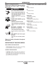
/"$(@4L8KC?B78<974@4:87
• Keep cylinder upright and chained to
support.
• Keep cylinder away from areas where
it may be damaged.
• Never lift welder with cylinder attached.
• Never allow welding electrode to touch cylinder.
• Keep cylinder away from welding or other live elec-
trical circuits.
+"+&Y%Y)"$Y)@4L
;4E@;84?G;BE><??
QShut off shielding gas supply when not
in use.
SEE AMERICAN NATIONAL STANDARD Z-49.1,
“SAFETY IN WELDING AND CUTTING” PUBLISHED
BY THE AMERICAN WELDING SOCIETY.
------------------------------------------------------------------------
-($$
$BG8 for Fast-Mate and European connector style
guns, connect gun to gun connector making
sure all pins and gas tube line up with appropri-
ate holes in connector. Tighten gun by turning
large nut on gun clockwise.
c. For GMA Gun Cables with separate gas fittings,
connect the 3/16” I.D. gas hose from the wire
drive unit to the gun cable barbed fitting.
d. For water cooled guns see WATER CONNEC-
TIONS in this section.