


-( (" "%$ ((")
)&%%")%(%")
*B#BHAG4"5>:(847<(88?&46>4:8
+F<A:G;8 #B?787 &?4FG<6 !&(847<(88?
74CG8E
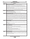
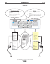
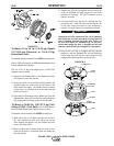
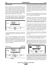
The Spindle should be located in the "%-(mounting hole.
1) Depress the Release Bar on the Retaining Collar
and remove it from the spindle. )88<:HE8
2) Place the Adapter on the spindle.
3) Re-install the Retaining Collar. Make sure that the
Release Bar “pops up” and that the collar retainers
fully engage the retaining groove on the spindle.
4) Rotate the spindle and adapter so the retaining
spring is at the 12 o'clock position.
5) Position the Readi-Reel so that it will rotate in a
direction when feeding so as to be de-reeled from
bottom of the coil.
6) Set one of the Readi-Reel inside cage wires on the
slot in the retaining spring tab.
7) Lower the Readi-Reel to depress the retaining
spring and align the other inside cage wires with
the grooves in the molded adapter.
8) Slide cage all the way onto the adapter until the
retaining spring "pops up" fully.
Check to be sure the Retaining Spring has fully
returned to the locking position and has SECURELY
locked the Readi-Reel Cage in place. Retaining
Spring must rest on the cage, not the welding elec-
trode.
------------------------------------------------------------------------
9) To remove Readi-Reel from Adapter, depress
retaining spring tab with thumb while pulling the
Readi-Reel cage from the molded adapter with
both hands. Do not remove adapter from spindle.
+*%$
%&(*%$
%*$
Hot inch occurs when the trigger is pulled and an arc
is not established. After a 2.5 second period, the
Sequencer will jump to the Weld state and the wire
feeder will run at the preset wire feed speed on the
display. The wire is hot (output is on) at this point.
Start, Upslope, Downslope, Crater, Burnback,
Postflow, etc are all skipped when Hot Inch is activat-
ed.
%%*#&*(%"
A Foot Amptrol Kit can be installed in order to operate
the output of the machine using a pedal. Located on
the Control Box, the Right encoder turns output on/off
if desired. The left encoder sets the max work point
limit. When the pedal is pressed OCV will be present
and gas will not flow. As soon as the tungsten touches
the work and there is current flow, the gas solenoid
will turn on. If the arc breaks the machine will enter
the postflow state. When the postflow timer expires,
the machine will return to OCV mode and no gas will
flow until the arc is established. If the pedal is
released it turns the machine off, postflow will be
entered until time out. When the postflow timer
expires the machine will return to idle state and wait
for trigger. Preflow will be presettable for external trig-
gers if desired. Triggering machine with encoder will
skip preflow.
-((,&%( +)*#$*)
"*(%&%"(*/
The system needs to be aware of the electrode polari-
ty. A DIP switch setting on the Wire Drive PC boards
is used for this purpose. See INSTALLATION Section
“Setting DIP Switches in the Wire Drive”.
(%.(*%
The systems needs to know which gear has been
installed on the Wire Drive, low or high speed. A DIP
switch setting on the Wire Drive PC boards is used for
this purpose. See INSTALLATION section“Wire Drive
Ratio” for information on how to set the DIP Switch.
&%-(R#+"-((