


A-1
INSTALLATION
POWER WAVE® C300
A-1
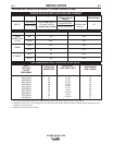
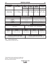
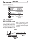
TECHNICAL SPECIFICATIONS - POWER WAVE® C300
RECOMMENDED INPUT WIRE AND FUSE SIZES
1
INPUT
VOLTAGE /
PHASE/
FREQUENCY
208/1/50/60
208/3/50/60
230/1/50/60
230/3/50/60
400/1/50/60
400/3/50/60
460/1/50/60
460/3/50/60
575/1/50/60
575/3/50/60
TIME DELAY FUSE
OR BREAKER
SIZE
2
(AMPS)
70
40
70
40
40
25
35
20
30
15
CORD SIZES
3
AWG SIZES (mm
2
)
6 (16)
8 (10)
6 (16)
8 (10)
10 (6)
12 (4)
12 (4)
14 (2.5)
12 (4)
14 (2.5)
INPUT AMPERE
RATING ON
NAMEPLATE
53
30
48
28
29
16
25
14
20
11
RATED OUTPUT
POWER SOURCE-INPUT VOLTAGE AND CURRENT
Model
K2675-1
Duty Cycle
40% rating
100% rating
Volts at Rated Amperes
29
26.5
31.2
29
22
20
Amperes
300
250
280
225
300
250
Duty Cycle
40%
100%
40%
100%
40%
100%
Process
GMAW
GMAW-Pulse
FCAW
SMAW
GTAW-DC
Input Amperes
(1 Phase in paren-
thesis)
30/28/16/14/11
(53/48/29/25/20)
23/21/12/11/9
(41/37/22/19/16)
Idle Power
300 Watts Max.
(fan on)
Power Factor @
Rated Output
.95
Input Voltage ± 10%
208/230/400*/460/575
1/3 phase 50/60 Hz
(* includes 380V to 415V)
1
Wire and Fuse Sizes based upon the U.S. National Electric Code and maximum output for 40°C (104°) ambient.
2
Also called “inverse time” or “thermal/magnetic” circuit breakers; circuit breakers that have a delay in tripping action that decreases as the
magnitude of current increases.
3
Type SO cord or similar in 30°C ambient.