


A-10
INSTALLATION
POWER WAVE® C300
A-10
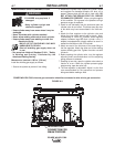
GUN USED
The Magnum 300 is the recommended gun for the
POWER WAVE® C300. Refer to the Magnum 300’s
operators manual for installation instructions.
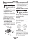
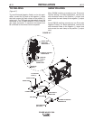
FEEDING ELECTRODE AND BRAKE
ADJUSTMENT
1. Turn the Reel or spool until the free end of the
electrode is accessible.
2. While tightly holding the electrode, cut off the bent
end and straighten the first 6" (150 mm). Cut off
the first 1" (25 mm). (If the electrode is not properly
straightened, it may not feed or may jam causing a
"birdnest".)
3. Insert the free end through the incoming guide
tube.
4. Press the Cold Inch key and push the electrode
into the drive roll.
5. Feed the electrode through the gun.
6. Adjust the brake tension with the thumbscrew on
the spindle hub, until the reel turns freely but with
little or no overrun when wire feeding is stopped.
Do not over tighten.
DRIVE ROLL PRESSURE SETTING
ELECTRIC SHOCK can kill.
• Turn the input power OFF at the weld-
ing power source before installation or
changing drive rolls and/or guides.
• Do not touch electrically live parts.
• When feeding with the gun trigger, unless
“COLD FEED” trigger mode is selected, the elec-
trode and drive mechanism are always “HOT” to
work and ground and could remain “HOT” sev-
eral seconds after the gun trigger is released.
• Do not operate with covers, panels or guards
removed or open
• Only qualified personnel should perform mainte-
nance work.
------------------------------------------------------------------------
The POWER WAVE® C300’s optimum drive roll pres-
sure varies with type of wire, surface condition, lubri-
cation, and hardness. Too much pressure could cause
birdnesting”, but too little pressure could cause wire
feed slippage with load and/or acceleration. The opti-
mum drive roll setting can be determined as follows:
1. Press end of gun against a solid object that is elec-
trically isolated from the welder output and press
the gun trigger for several seconds.
2. If the wire "birdnests", jams, or breaks at the drive
roll, the drive roll pressure is too great. Back the
pressure setting out turn, run new wire through gun,
and repeat above steps.
3. If the only result is drive roll slippage, disengage the
gun, pull the gun cable forward about 6" (150 mm).
There should be a slight waviness in the exposed
wire. If there is no waviness, the pressure is too
low. Increase the pressure setting turn, reconnect
the gun, tighten locking clamp and repeat the above
steps.
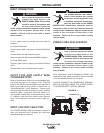
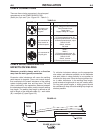
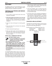
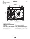
PRESSURE ARM ADJUSTMENT
The pressure arm controls the amount of force the drive
rolls exert on the wire. Proper adjustment of pressure
arm gives the best welding performance.
Set the pressure arm as follows (See Figure A.6):
Aluminum wires between 1 and 3
Cored wires between 3 and 4
Steel, Stainless wires between 4 and 6
FIGURE A.6
ALUMINUM
FLUX CORE
ARC WELDING
GAS METAL
ARC WELDING
6
1
3
2
5
4
Aluminum wires
Cored wires
Steel, Stainless wires