


A-6
INSTALLATION
POWER WAVE® C300
A-6
3
3
44
22
1
1
AA
BB
C
C
DD
F
F
EE
AA
BB
GG
CC
DD
F
F
EE
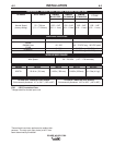
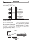
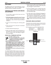
Function
4-pin trigger con-
nector for push-
only guns.
6-pin connector for
remote control or
foot/hand amptrol.
7-pin connector for
push-pull guns
PIN
1
2
3
4
A
B
C
D
E
F
A
B
C
D
E
F
G
Wiring
Supply Voltage for Dual Procedure
Dual Procedure Input
Trigger Input
Supply Voltage for Trigger
77 Remote potentiometer, 5K
75 Remote potentiometer, common
76 Remote potentiometer, wiper
Switch, On/Off
Switch, common
Not used
Motor -
Motor +
77 Remote potentiometer, 5K
76 Remote potentiometer, wiper
Switch, On/Off
Switch, common
75 Remote potentiometer, common
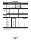
TABLE A.1
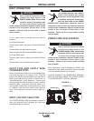
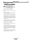
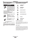
FIGURE A.3
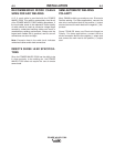
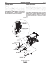
CABLE CONNECTIONS
There are three circular connectors in the wire spool
compartment on the POWER WAVE® C300.
(See 4-pin, 6-pin and 7-pin---Figure A.2---Table A.1)
B
A
C
POWER
WAVE
WORK
CABLE INDUCTANCE AND ITS
EFFECTS ON WELDING
Whenever possible always weld in a direction
away from the work (ground) connection.
Excessive cable inductance will cause the welding
performance to degrade. There are several factors
that contribute to the overall inductance of the cabling
system including cable size, and loop area. The loop
area is defined by the separation distance between
the electrode and work cables, and the overall welding
loop length. The welding loop length is defined as the
total of length of the electrode cable (A) + work cable
(B) + work path (C) (see Figure A.3).
To minimize inductance always use the appropriate
size cables, and whenever possible, run the electrode
and work cables in close proximity to one another to
minimize the loop area. Since the most significant fac-
tor in cable inductance is the welding loop length,
avoid excessive lengths and do not coil excess cable.
For long work piece lengths, a sliding ground should
be considered to keep the total welding loop length as
short as possible.
FIGURE A.2