


%*+##+ &%
-%+S
#&+ &%%-%+ #+ &%
The welder should be located to provide an unrestrict-
ed flow of clean, cool air to the cooling air inlets and to
avoid restricting the cooling air outlets. Also, locate
the welder so that the engine exhaust fumes are prop-
erly vented to an outside area.
*+" %
VANTAGE® 300 machines cannot be stacked.
%#&&')+ &%
Engines are designed to run in the level condition
which is where the optimum performance is achieved.
The maximum angle of continuous operation is 20
degrees in all directions, 30 degrees Intermittent (less
than 10 minutes continuous) in all directions. If the
engine is to be operated at an angle, provisions must
be made for checking and maintaining the oil level at
the normal (FULL) oil capacity in the crankcase.
When operating the welder at an angle, the effective
fuel capacity will be slightly less than the amount
specified.
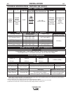
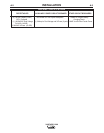
*+0'),+ &%*
&@>KCG3>;8;76B7DEA@@7>E:AG>6;@EF3>>
GE7ADE7DH;57F:;E7CG;B?7@F
A@AF3FF7?BFFAGE7F:;E7CG;B?7@FG@F;>KAG
:3H7F:ADAG9:>KD736F:77@9;@7?3@G835FGD7D\E
?3@G3>EGBB>;76I;F:KAGDI7>67D F;@5>G67E
;?BADF3@FE387FKBD753GF;A@E67F3;>767@9;@7
EF3DF;@9AB7D3F;@93@6?3;@F7@3@57;@EFDG5F;A@E
3@6B3DFE>;EFE
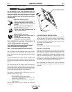
#+) *&"53@=;>>
RA@AFFAG5:7>75FD;53>>K>;H7B3DFEAD
7>75FDA67I;F:E=;@ADI7F5>AF:;@9
R @EG>3F7 KAGDE7>8 8DA? IAD= 3@6
9DAG@6
R>I3KEI73D6DK;@EG>3F;@99>AH7E
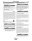
% %[/,*+[53@=;>>
R,E7;@AB7@I7>>H7@F;>3F763D73EAD
H7@F7J:3GEFAGFE;67
$&- %')+*[53@;@<GD7
RA@AFAB7D3F7I;F:6AADEAB7@AD
9G3D6EA88
R*FAB7@9;@7478AD7E7DH;5;@9
R"77B3I3K8DA??AH;@9B3DFE
*77 366;F;A@3> I3D@;@9;@8AD?3F;A@ 3F
8DA@FA8F:;EAB7D3FAD\E?3@G3>
.)% %
-)-&#+),+ &%-
The VRD feature provides additional safety in the CC-Stick
mode especially in an environment with a higher risk of
electric shock such as wet areas and hot humid sweaty
conditions.
The VRD reduces the OCV (Open Circuit Voltage) at the
welding output terminals while not welding to less than 13V
DC when the resistance of the output circuit is above 200Ω
(ohms).
The VRD requires that the welding cable connections be
kept in good electrical condition because poor connections
will contribute to poor starting. Having good electrical con-
nections also limits the possibility of other safety issues
such as heat-generated damage, burns and fires.
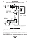
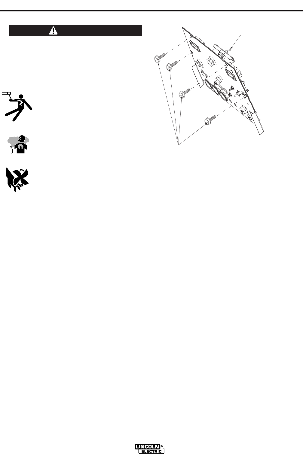
The machine is shipped with the VRD switch in the “Off”
position. To turn it “On” or “Off”.
• Turn the engine “Off”.
• Disconnect the negative battery cable.
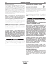
• Lower the control panel by removing 4 front
panel screws.
(See Figure A.1)
• Place the VRD switch in the “On” or “Off” position.
(See Figure A.1)
With the VRD switch in the “On” position, the VRD lights
are enabled.
(VRD)-VOLTAGE REDUCTION DEVICE
SWITCH IS LOCATED IN THIS AREA.
REMOVE 4 FRONT PANEL
SCREWS TO ACCESS
(
VRD) SWITCH
(VRD)-VOLTAGE REDUCTION DEVICE
SWITCH IS LOCATED IN THIS AREA.
REMOVE 4 FRONT PANEL
SCREWS TO ACCESS
(
VRD) SWITCH
,)