


&')+ &%
-%+S
+0' #-%+S,#&%*,$'+ &%
7GFL#
3>D#;F7DED
---------
.34 (1.30)
---------
.46 (1.75)
-----------
.64 (2.41)
-----------
.86 (3.24)
-------------
1.22 (4.62)
1.10 (4.15)
.89 (3.36)
.73 (2.75)
.58 (2.18)
)G@@;@9+;?78AD
93>>A@EAGDE
--------
58.41
--------
43.28
--------
31.39
--------
23.36
--------
16.37
18.23
22.51
27.53
35.41
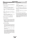
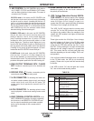
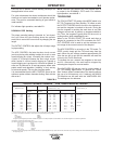
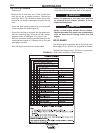
1400 R.P.M.
1800 R.P.M.
DC Weld Output 150 Amps @ 20 Volts
DC Weld Output 250 Amps @ 24 Volts
DC Weld Output 300 Amps @ 32 Volts
10,000 Watts
7,500 Watts
5,000 Watts
2,500 Watts
%&+ This data is for reference only. Fuel consumption is approximate and can be influenced
by many factors, including engine maintenance, environmental conditions and fuel quality.
Low Idle - No Load
High Idle - No Load
*+&'' %+% %
Remove all welding and auxiliary power loads and
allow the engine to run at low idle speed for a few
minutes to cool the engine.
*+&'the engine by placing the RUN-STOP switch in
the STOP position.
%&+ A fuel shut off valve is located on the fuel pre-
filter.
.#)&')+ &%
,+00#
Duty Cycle is the percentage of time the load is being
applied in a 10 minute period. For example a 60% duty
cycle, represents 6 minutes of load and 4 minutes of no
load in a 10 minute period.
#+)& %&)$+ &%
For any electrode the procedures should be kept with-
in the rating of the machine. For information on elec-
trodes and their proper application see (www.lincoln-
electric.com) or the appropriate Lincoln publication.
The VANTAGE® 300 can be used with a broad range of
DC stick electrodes. The MODE switch provides two
stick welding settings as follows:
&%*+%+,))%+*+ ".# %
The CC-STICK position of the MODE switch is designed
for horizontal and vertical-up welding with all types of
electrodes, especially low hydrogen. The OUTPUT CON-
TROL dial adjusts the full output range for stick welding.
The ARC CONTROL dial sets the short circuit current
(arc-force) during stick welding to adjust for a soft or
crisp arc. Increasing the number from -10(soft) to
+10(crisp) increases the short circuit current and pre-
vents sticking of the electrode to the plate while welding.
This can also increase spatter. It is recommended that
the ARC CONTROL be set to the minimum number with-
out electrode sticking. Start with the dial set at 0.
%&+ Due to the low OCV with the VRD on, a very
slight delay during striking of the electrodes may
occur. Due to the requirement of the resistance in the
circuit to be low for a VRD to operate, a good metal-
to-metal contact must be made between the metal
core of the electrode and the job.
A poor connection anywhere in the welding output cir-
cuit may limit the operation of the VRD. This includes
a good connection of the work clamp to the job. The
work clamp should be connected as close as practical
to where the welding will be performed.
AD%7I>75FDA67E
E6010 - Touch, Lift to Start the Arc
E7018, E7024 - Touch, Rock Back and Forth in Joint,
Lift .
Once the arc is started, normal welding technique for
the application is then used.
AD)7*FD;=;@9>75FDA67E
Some electrodes form a cone at the end of the elec-
trode after the welding arc has been broken, particu-
larly iron powder and low hydrogen electrodes. This
cone will need to be broken off in order to have the
metal core of the electrode make contact.
E6010 - Push, Twist in Joint, Lift
E7018, E7024 - Push, Rock Back and Forth in Joint,
Lift.
+#