


%*+##+ &%
-%+S
#+) #&%%+ &%*
$ %)&,% %
Because this portable engine driven welder creates its
own power, it is not necessary to connect its frame to
an earth ground, unless the machine is connected to
premises wiring (home, shop, etc.)
To prevent dangerous electric shock, other equipment
to which this engine driven welder supplies power
must:
R79DAG@676FAF:78D3?7A8F:7I7>67DGE;@93
9DAG@676FKB7B>G9
R76AG4>7;@EG>3F76
RA@AF9DAG@6F:7?35:;@7FA3B;B7F:3F53DD;7E
7JB>AE;H7AD5A?4GEF;4>7?3F7D;3>
------------------------------------------------------------------------
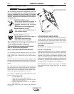
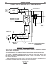
When this welder is mounted on a truck or trailer, its
frame must be electrically bonded to the metal frame
of the vehicle. Use a #8 or larger copper wire connect-
ed between the machine grounding stud and the
frame of the vehicle. When this engine driven welder
is connected to premises wiring such as that in a
home or shop, its frame must be connected to the
system earth ground. See further connection instruc-
tions in the section entitled "Standby Power
Connections" as well as the article on grounding in the
latest National Electrical Code and the local code.
In general, if the machine is to be grounded, it should
be connected with a #8 or larger copper wire to a solid
earth ground such as a metal water pipe going into
the ground for at least ten feet and having no insulat-
ed joints, or to the metal framework of a building
which has been effectively grounded.
The National Electrical Code lists a number of alter-
nate means of grounding electrical equipment. A
machine grounding stud marked with the symbol
is provided on the front of the welder.
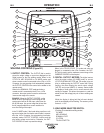
.# %+)$ %#*
The VANTAGE® 300 is equipped with a toggle switch
for selecting "hot" welding terminal when in the
"WELD TERMINALS ON" position or "cold" welding
terminal when in the "REMOTELY CONTROLLED"
position.
)$&+&%+)&#
The VANTAGE® 300 is equipped with a 6-pin and a
14-pin connector. The 6-pin connector is for connect-
ing the K857 or K857-1 Remote Control or for TIG
welding, the K870 foot Amptrol or the K963-3 hand
Amptrol. When in the CC-STICK, Arc Gouging, or CV-
WIRE modes and when a remote control is connected
to the 6-pin Connector, the auto-sensing circuit auto-
matically switches the OUTPUT control from control at
the welder to remote control.
When in TOUCH START TIG mode and when a
Amptrol is connected to the 6-Pin Connector, the
OUTPUT dial is used to set the maximum current
range of the CURRENT CONTROL of the Amptrol.
When in the DOWNHILL PIPE mode and when a remote control
is connected to the 6-Pin or 14-Pin connector, the output control
is used to set the maximum current range of the remote.
/$'#When the OUTPUT CONTROL on the welder is set
to 200 amps the current range on the remote control will be 40-
200 amps, rather than the full 40-300 amps. Any current range
that is less than the full range provides finer current resolution
for more fine tuning of the output.
The 14-pin connector is used to directly connect a
wire feeder control cable.
In the CV-WIRE mode, if the
feeder being used has a voltage control when the wire feeder
control cable is connected to the 14-Pin Connector, the auto-
sensing circuit automatically makes OUTPUT CONTROL inac-
tive and the wire feeder voltage control active. Otherwise, the
OUTPUT CONTROL is used to preset the voltage.
%&+.:7@3I;D787767DI;F:34G;>F;@I7>6;@9
HA>F3975A@FDA>;E5A@@75F76FAF:7B;@5A@@75
FAD6A@AF5A@@75F3@KF:;@9FAF:7B;@5A@@75
FAD
------------------------------------------------------------------------
.)% %
.)% %