


A-3
INSTALLATION
POWER FEED 10 / R
A-3
When using an inverter type power source, Use the
largest welding (electrode and work) cables that are
practical. At least 2/0 copper wire - even if the aver-
age output current would not normally require it.
When pulsing, the pulse current can reach very high
levels. Voltage drops can become excessive, leading
to poor welding characteristics, if undersized welding
cables are used.
Connect the one end of the electrode cable, to the
power source output terminal of the desired polarity.
Connect the other end of the electrode cable to the
wire drive feed plate using the stud, lockwasher, and
nut provided on the wire drive feed plate. The elec-
trode cable lug must be against the feed plate. Be
sure the connection to the feed plate makes tight
metal-to-metal electrical contact. The electrode cable
should be sized according to the specifications given
in the work cable connections section.
NEGATIVE ELECTRODE POLARITY
When negative electrode polarity is required, such as
in some Innershield applications, reverse the output
connections at the power source (electrode cable to
the negative (-) stud, and work cable to the positive
(+) stud).
When operating with electrode polarity negative the
switch 7 must be set to OFF.
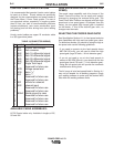
Set the Negative Polarity switch on Wire Feed Head
PC board as follows: These instructions apply to
the Power Wave 455/R and Power Wave 655/R.
Consult the manual for the power source if necessary.
1. Turn off power to the power source at the dis-
connect switch.
2. Remove the front cover from the power source.
3. The wire feed head board is on the right side of the
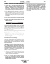
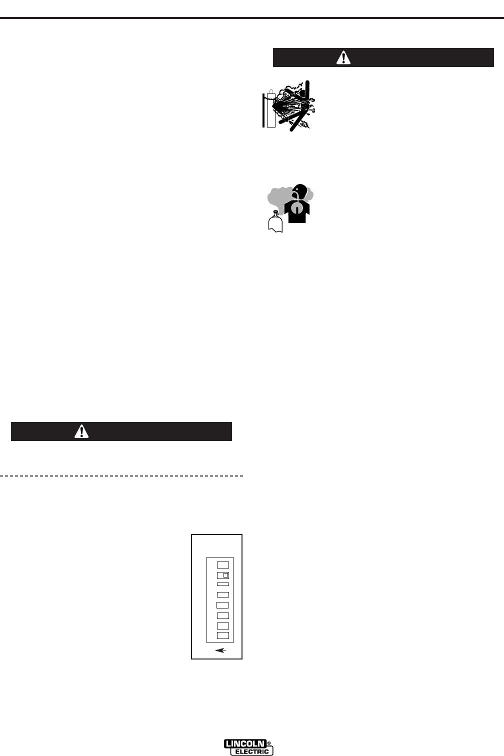
power source. Locate the 8-position DIP
switch and look for switch 7 of the DIP
switch.
4. Using a pencil or other small object,
slide the switch to the ON position for
negative electrode polarity. Conversely,
slide the switch to the OFF position for
positive electrode polarity.
5. Replace the cover and screws. The PC board will
“read” the switch at power up, automatically adjust-
ing all control parameters for the speed range
selected.
SHIELDING GAS CONNECTION
The customer must provide a cylinder of shielding
gas, a pressure regulator, a flow control valve, and a
hose from the flow valve to the gas inlet fitting of the
wire drive unit.
Connect a supply hose from the gas cylinder flow
valve outlet to the 5/8-18 female inert gas fitting on the
back panel of the wire drive or, if used, on the inlet of
the Gas Guard regulator.
CONTROL CABLE
CONTROL CABLE CONNECTIONS
The Power Wave / Power Feed Wire Feeders offer
flexibility in the connection of system components.
This system uses the same type of control cable
between all of the system components. Connections
can be “daisy chained” from one system component to
another. Components can be connected in any order,
as long as the proper input and output receptacles are
present.
Connect the control cable from the Power Feed 10
Robotic Wire Drive to the output receptacle on the
PowerWave.
NOTE: The maximum cable length between the
Power Feed 10 Robotic and the power source
is 100 feet (33 m).
O
N
1 2 3 4 5 6 7 8
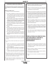
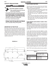
CYLINDER may explode if damaged.
• Keep cylinder upright and chained
to support.
• Keep cylinder away from areas
where it may be damaged.
• Never lift welder with cylinder attached.
• Never allow welding electrode to touch cylin-
der.
• Keep cylinder away from welding or
other live electrical circuits.
BUILDUP OF SHIELDING GAS may
harm health or kill.
• Shut off shielding gas supply when
not in use.
SEE AMERICAN NATIONAL STANDARD Z-49.1,
“SAFETY IN WELDING AND CUTTING” PUB-
LISHED BY THE AMERICAN WELDING SOCIETY.
------------------------------------------------------------------------
WARNING
WARNING