


A-2
INSTALLATION
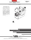
POWER FEED 10 / R
A-2
SAFETY PRECAUTIONS
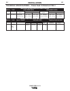
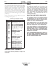
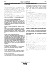
MOUNTING OF THE PF10/R
Mount the wire drive unit by means of the 4 holes in
the bottom of the wire drive base. Note that the gear-
box assembly is electrically “hot” when welding.
Therefore, make certain the gearbox does not come in
contact with the structure on which the unit is mount-
ed. The wire feed unit should be mounted so that the
drive rolls are in a vertical plane to prevent the accu-
mulation of dirt in the drive roll area. Do not bend the
conduit more than 45°.
FIGURE A.1
ELECTRODE ROUTING
The electrode supply may be either from reels, Readi-
Reels, spools, or bulk packaged drums or reels.
Observe the following precautions:
• Do not bend the conduit more than 45°, and to use
the minimum amount of conduit necessary for the
wire reel to connect to the wire feeder.
• The electrode is "hot" while welding and must be
insulated from the boom, conduit and wire payoff
structure.
• If more than one wire feed unit shares the same
boom and are not sharing the some power source
output stud, their wire and reels must be insulated
from each other as well as insulated from their
mounting structure.
ELECTRODE AND WORK CABLE CON-
NECTIONS
Most welding applications run with the electrode being
positive (+). For those applications, connect the elec-
trode cable between the wire feeder and the positive
(+) output stud on the power source (located beneath
the spring loaded output cover near the bottom of the
case front).
A work lead must be run from the negative (-) power
source output stud to the work piece. The work piece
connection must be firm and secure, especially if
pulse welding is planned. Excessive voltage drops at
the work piece connection often result in unsatisfacto-
ry pulse welding performance.
Connect a work lead of sufficient size and length (per
TABLE 1) between the proper output terminal on the
power source and the work. Be sure the connection
to the work makes tight metal-to-metal electrical con-
tact. To avoid interference problems with other equip-
ment and to achieve the best possible operation, route
all cables directly to the work or wire feeder. Do not
bundle the electrode and work leads tightly together.
Avoid excessive lengths and do not coil excess cable.
Use K1796 Coaxial welding cables wherever possible.
Minimum work and electrode cables sizes are as follows:
TABLE 1
Current (60% Duty Cycle)
400 Amps
500 Amps
600 Amps
ELECTRIC SHOCK can kill.
• Only qualified personnel should
perform this installation.
• Turn off the input power to the power source at
the disconnect switch or fuse box before work-
ing on this equipment. Turn off the input power
to any other equipment connected to the weld-
ing system at the disconnect switch or fuse
box before working on this equipment.
• Do not touch electrically hot parts.
• Always connect the Power Wave grounding lug
(located inside the reconnect input access
door) to a proper safety (Earth) ground.
----------------------------------------------------------------------------------------
MINIMUM COPPER WORK
CABLE SIZE, AWG
Up To-100 Ft. Length (30 m)
2/0 (67 mm2)
3/0 (85 mm2)
3/0 (85 mm2)
WARNING
7.11
1.77
1.77
1.97
3.05
.25 DIA.
(4 Places)
.22 DIA.
(2 Places)