


A-4
INSTALLATION
POWER FEED 10 / R
A-4
CONTROL CABLE SPECIFICATIONS
It is recommended that genuine Lincoln control cables
be used at all times. Lincoln cables are specifically
designed for the communication and power needs of
the Power Wave / Power Feed system. The use of
non-standard cables, especially in lengths greater
than 25 feet, can lead to communication problems
(system shutdowns), poor motor acceleration (poor
arc starting) and low wire driving force (wire feeding
problems).
Lincoln control cables are copper 22 conductor cable
in a SO-type rubber jacket.
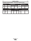
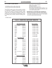
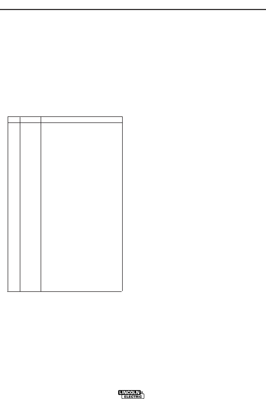
TABLE 2 (CONNECTOR WIRING)
AVAILABLE CABLE ASSEMBLIES:
K1795 Control cable only. Available in lengths of 25',
50' and 100'.
WIRE DRIVE GEAR RATIO (HIGH OR LOW
SPEED)
The speed range capability and drive torque of the
Power Feed wire drives can be easily and quickly
changed by changing the external drive gear. The
Power Feed Wire Feeders are shipped with both high
speed and a low speed gears. As shipped from the
factory, the low speed (high torque) gear is installed
on the feeder. If this is the desired gear ratio, no
changes need be made.
SELECTING THE PROPER GEAR RATIO
See Specification Section A-1 for feed speed and wire
size capabilities with high and low speed gear ratios.
To determine whether you should be using the high or
low speed ratio use the following guidelines:
• If you need to operate at wire feed speeds above
800 IPM (20 m/m), you will need to install the high
speed gear (large 30 tooth, 1.6 inch diameter gear).
• If you do not need to run at wire feed speeds in
excess of 800 IPM (20 m/m), you should use the low
speed gear (small, 20 tooth, 1.1 inch diameter gear).
Using the low speed ratio will provide the maximum
available wire driving force.
The full range of wire feed speed listed in Section A-1
may not be useable for all welding programs. Check
your welding software to make sure the desired WFS
falls within the welding software limits.
Pin
A
B
C
D
E
F
G
H
I
J
K
L
M
N
P
R
S
T
U
V
W
X
Lead #
841
844
842
843
845
846
847
67B
539
541
521
522
855A
Function
+15vdc Tach voltage
Tach common
Tach 1A differential signal
Tach 1B differential signal
Tach 2A differential signal
Tach 2B differential signal -
Single Tach Input
Reserved for future use
Voltage sense lead
Motor "+"
Motor "-"
Reserved for future use
Reserved for future use
+40vdc for solenoid
solenoid input
Reserved for future use
Reserved for future use
Shield ground to case
Reserved for future use
Reserved for future use
Reserved for future use
Reserved for future use