


A-6
INSTALLATION
POWER FEED 10 / R
A-6
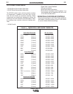
WIRE FEED DRIVE ROLL KITS
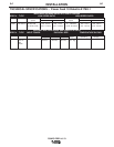
NOTE: The maximum rated solid and cored wire
sizes and selected drive ratios are shown on
the SPECIFICATIONS in the front of this sec-
tion.
The electrode sizes that can be fed with each roll and
guide tube are stenciled on each part. Check the kit
for proper components. Kit specifications can be
found in the ACCESSORIES section.
PROCEDURE TO INSTALL DRIVE ROLLS
AND WIRE GUIDES
DRIVE ROLL KIT INSTALLATION (KP1505-[ ])*
(KP1507-[ ])*
1. Turn OFF Welding Power Source.
2. Pull open Pressure Door to expose rolls and wire
guides.
3. Remove Outer Wire Guide by turning knurled
thumb screws counter-clock-wise to unscrew them
from Feedplate.
4. Remove drive rolls, if any are installed, by pulling
straight off shaft. Remove inner guide.
5. Insert inner Wire Guide, groove side out, over the
two locating pins in the feedplate.
6. Install each drive roll by pushing over shaft until it
butts up against locating shoulder on the drive roll
shaft. (Do Not exceed maximum wire size rating of
the wire drive).
7. Install Outer Wire Guide by sliding over locating
pins and tightening in place.
8. Engage upper drive rolls if they are in the “open”
position and close Pressure Door.
TO SET DRIVE ROLL PRESSURE, see “Drive Roll
Pressure Setting” in OPERATION.
GENERAL GUN CONNECTION GUIDELINES
The instructions supplied with the gun and K1500
series gun adapter should be followed when installing
and configuring a gun. The following guidelines are
general procedures only that are not intended to cover
all guns.
1. Check that the drive rolls and guide tubes are prop-
er for the electrode size and type being used.
2. Lay the cable out straight. Insert the connector on
the welding conductor cable into the brass conduc-
tor block on the front of the wire drive head. Make
sure it is all the way in and tighten the hand clamp.
Keep this connection clean and bright.
Note: For Fast-Mate and European connector style
guns, connect gun to gun connector making
sure all pins and gas tube line up with appropri-
ate holes in connector. Tighten gun by turning
the large nut on gun clockwise.
3. For GMA Gun Cables with separate gas fittings,
connect the gas hose from the wire drive unit to the
gun cable barbed fitting.
*See ACCESSORIES SECTION Table C.1, page C-1.
WARNING
WARNING
Observe all additional Safety Guidelines detailed
throughout this manual.
ELECTRIC SHOCK can kill.
• Do not touch electrically live parts such
as output terminals or internal wiring.
•
When feeding without Power Feed 10 “Cold
Feed” feature, electrode and drive mechanism
are “hot” to work and ground and could remain
energized several seconds after the gun trigger
is released.
• Turn OFF input power at welding power
source before installation or changing drive
roll and/or guide tubes.
• Welding power source must be connected
to system ground per the National Electrical
Code or any applicable local codes.
• Only qualified personnel should
perform this installation.