


B-2
OPERATION
B-2
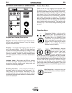
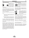
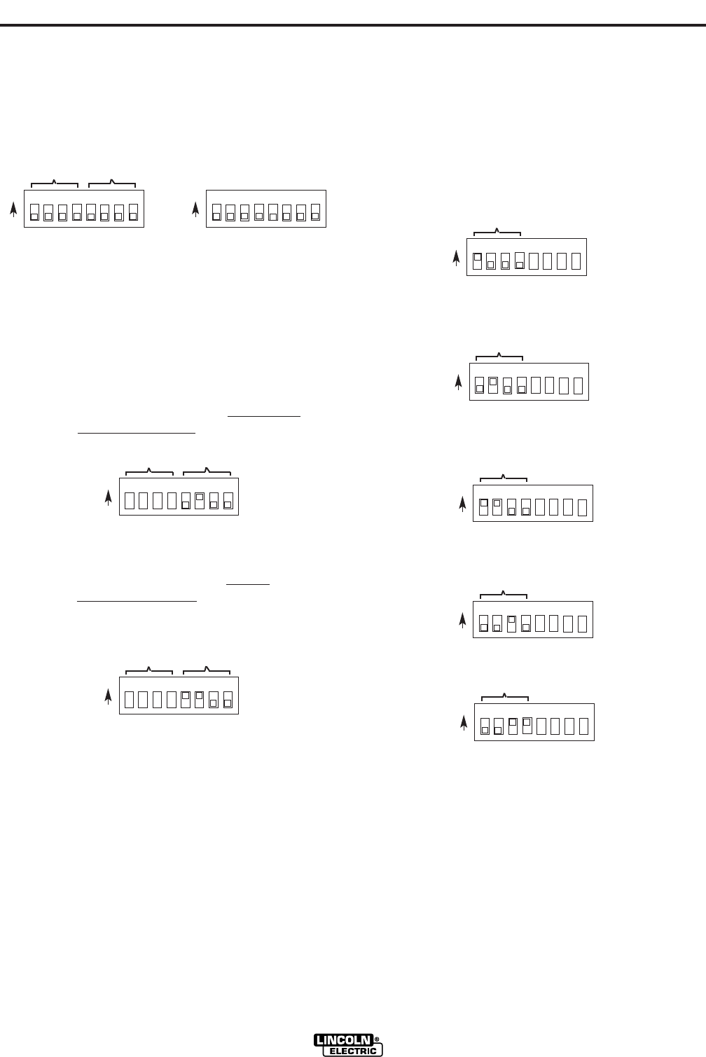
Setting the DIP Switches
The DIP switches are each labeled with an “ON”
arrow showing the on direction for each of the 8 indi-
vidual switches in each DIP switch (S1 and S2). The
functions of these switches are also labeled and set
as described below:
Wire Drive Head Selection
The LN-10 control is set up for proper presettable wire
feed speed by setting S1 DIP switches (5 to 8) as
appropriate per the following examples for the head
specification and 10 Series wire drive external gear
selection being used:
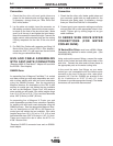
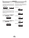
For K1559-5 (LN-10 Bench) with 35-500 IPM
(0.89-
12.7 m/m) Low Speed Ratio set S1 DIP Switch as
follows:
For K1559-5 (LN-10 Bench) with 50-750
IPM (1.25-
19.0 m/m) High Speed Ratio
set S1 DIP Switch as
follows: (initial factory setting)
LN-10
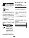
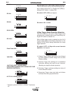
Welding Power Source Selection
The LN-10 Control is set up for proper presettable
weld voltage control by setting S1 DIP switches (1 to
4) as appropriate per the following information for the
welding power source being used:
CV-250/CV 300-I:
CV-300/CV 400-I:
CV-400/CV 500-I:
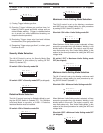
CV-655: (initial factory setting)
V350-PRO And V450-PRO:
Pwr Sources
S1
ON
S1
12345678
Pwr Sources
S1
ON
S1
12345678
Pwr Sources
S1
ON
S1
12345678
Pwr Sources
S1
ON
S1
12345678
Pwr Sources
S1
ON
S1
12345678
Pwr Sources
S1
ON
S1
12345678
M 4 S R + -
S2
ON
S2
12345678
Head
Pwr Sources
S1
ON
S1
12345678
Head
Pwr Sources
S1
ON
S1
12345678
Head