


B-3
OPERATION
B-3
PURGE - COLD INCH SWITCH (OPTIONAL). This
control, located on the optional K418 GMA Timer Kit,
provides control of some wire feeder functions without
energizing the welding power source. The momentary
up position energizes the gas solenoid but not the wire
feeder or welding power source. The momentary down
position energizes the wire feeder but not the gas
solenoid or the welding power source.
ELECTRODE POLARITY SWITCH (OPTIONAL).
This switch, located on the optional K416 Digital and
K417 Analog Meter Kits, controls the polarity of the
meter. Set this switch to the same polarity as the
electrode lead to allow correct operation of the meter.
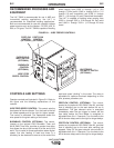
CIRCUIT PROTECTION
A manual reset circuit breaker protects the AC supply
line and the wire feeder from overloads, usually
caused by excessive wire drag or other wire feed
problems. To reset the circuit breaker, raise the cover
of the wire drive compartment and push the white
button on the side of the control box above the drive
rolls.
The LN-7 and LN-7 GMA also include a Ground Lead
Protector (GLP) circuit and fuse in the 2-4 contactor
circuit.
The frame of the LN-7 wire feed unit is grounded to the
frame of the power source by a lead in the control
cable. The GLP circuit prevents welding current from
damaging this lead if the electrode circuit touches the
wire feeder frame while the gun trigger is pressed.
When the protector circuit is tripped, the wire feed rolls
will not turn and the welding contactor in the power
source will not close when the gun trigger is pressed.
To reset the protector circuit, press the red button
above the drive rolls and to the left of the circuit
breaker. There is no visual indication when the
protector circuit is tripped.
AVOIDING GROUND LEAD
PROTECTOR (GLP) ACTIVATION
DO NOT allow the electrode to contact the case of the
wire feeder or the uninsulated part of the wire reel
stand when the gun trigger is activated.
Be sure that all work lead connections to the work
make tight metal-to-metal contact.
DO NOT allow excess input cable or work cable to be
placed closer than three feet from the wire feeder.
DO NOT coil excess input cable assembly or use a
coiled assembly as shipped from the factory. Instead,
loop the excess cable length back and forth in three to
six foot straight lengths. Coiling the input cable results
in a transformer action between the electrode
conductor cable and the ground lead in the
multiconductor control cable. This transformer action
can cause a current to flow in the ground lead which
will falsely activate the GLP circuit.
To reset the GLP circuit, press the red button above
the drive rolls and to the left of the circuit breaker.
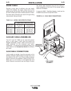
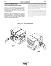
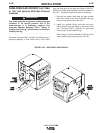
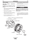
DRIVE ROLL INSTALLATION
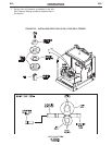
CHANGING DRIVE ROLLS FOR TWO-
ROLL WIRE FEEDERS:
To change drive rolls on a two-roll wire feeder, refer to
Figure B.2 and perform the following steps:
1. Rotate the latch knob on the quick release arm.
2. Remove the hex head screw and clamping collar.
Remove the drive roll from the shaft.
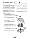
3. The new roll to be installed is stamped for the size to
be fed. An “A” after the size indicates aluminum wire.
Remove the rolls from the kit and wipe them clean.
Wipe the output shaft and locating shoulder clean.
4. Use the drive key, clamping collar, and hex head
screw to install the roll on the output shaft. Certain
size drive rolls consist of two roll halves, and may
contain a spacer. If the drive roll you are installing
contains a spacer, the spacer fits between the two
halves of the drive roll. Tighten the hex head
screw.
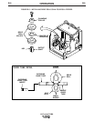
5. Back out the guide tube clamping screws.
Remove the old guide tubes, if installed.
6. Insert the outgoing guide tube (the one with the
plastic insert) into the front hole. If the guide tube
has a non-symmetrical chisel end, the larger
radius must face the drive roll. See Figure B.2.
Push the guide tube back as far as it will go and
tighten the clamping screw. Insert the incoming
guide tube as far back as it will go and tighten the
clamping screw. The clamping screws are dog
points. When the guide tubes are properly
installed these dog points will lock into the annular
grooves in each of the guide tubes.
LN-7 & LN-7 GMA