


8
CAUTION:
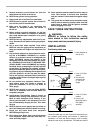
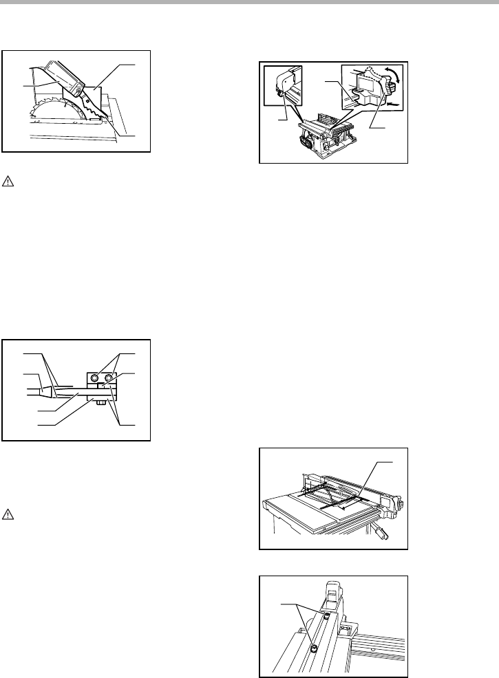
• Before installing the blade guard, adjust the depth
of cut to its maximum elevation.
Remove the center cover and push the button inside the
hole sideways. With the button so pushed, insert the
blade guard into the blade guard mounting portion (stay).
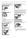
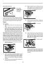
The spreader installing location is factory-adjusted so
that the blade and spreader will be in a straight line. How-
ever, if they are not in a straight line, loosen the hex bolts
with hex wrench and adjust the blade guard mounting
portion (stay) so that the spreader is aligned directly
behind the blade. Then tighten the hex bolts to secure
the stay.
CAUTION:
• If the blade and spreader are not aligned properly, a
dangerous pinching condition may result during
operation. Make sure they are properly aligned. You
could suffer serious personal injury while using the
tool without a properly aligned spreader.
• NEVER make any adjustments while tool is
running. Disconnect the tool before making any
adjustments.
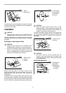
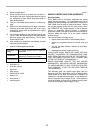
Installing and adjusting rip fence
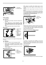
1) Fit the hook on the tip of the rip fence into the far guide
rail on the table or sub table (R) and install and push the
rip fence forward so that the fence holder engages with
the nearmost guide rail.
To slide the rip fence on the guide rail sideways, pivot the
knob on the fence holder to the half way of its travel.
To secure the rip fence, pivot fully the knob on the fence
holder.
2) To slide the rip fence on the guide rail sideways, return
the knob on the fence holder fully without pulling the lever
on the knob.
3) To remove it, pull the lever on the knob and pivot the
knob fully forward while pulling the lever.
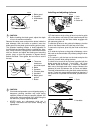
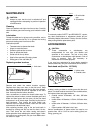
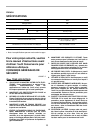
To check to be sure that the rip fence is parallel with the
blade, secure the rip fence 2 - 3 mm (5/64” - 1/8” ) from
the blade. Raise the blade up to maximum elevation.
Mark one of the blade teeth with a crayon. Measure the
distance (A) and (B) between the rip fence and blade.
Take both measurements using the tooth marked with the
crayon. These two measurements should be identical. If
the rip fence is not parallel with the blade, proceed as fol-
lows:
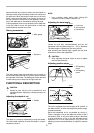
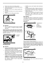
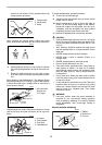
1. Blade guard
2. Spreader
3. Antikickback
pawl
1. These two
clearances
should be equal
2. Blade
3. Spreader
4. Pressure plate
5. Hex bolts
6. Blade guard
portion
7. Button
1
2
3
006139
1
2
3
4
5
6
7
006141
1. Hook
2. Knob
3. Guide rail
1. Scale
1. Hex bolts
1
3
2
006159
1
B
A
006160
1
006161