P 12/ 12
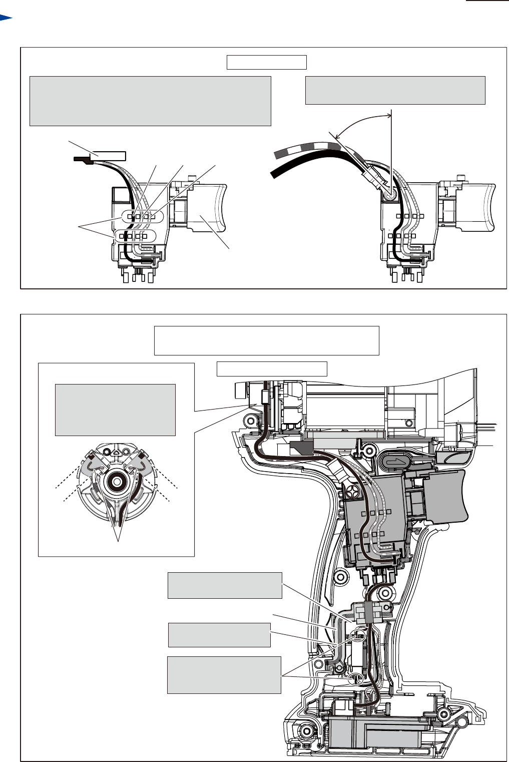
Wiring diagram
Wiring to Switch
Connect Lead wires to Switch, tilting their
Connectors to 45 degrees as dran below.
FET
Fix FET Lead wires as follows:
yellow with Lead wire holder nearest to Switch trigger
blue with the center Lead wire holder
black with Lead wire holder farthest from Switch trigger
Lead wire
holder
yellow
blue
black
Switch trigger
FET
Fig. D-4A
Fig. D-5A
Wiring in Housing set (L)
Seal
Put the bundled Lead wires
into the groove of Sponge.
Pay attention not to put
Lead wires on the Seal.
Lead wires connected to
Connector have to be fixed
with Lead wire holders.
45 degrees
without Battery fuel gauge
available exclusively for North American countries
Brush holder complete
Put Pigtail of Carbon brush
in the area marked with gray
color to avoid pinching with
Rear cover.
Pigtail of Carbon brush
9 mm
9 mm


