


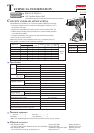
P 4/ 12
Repair
[3] DISASSEMBLY/ASSEMBLY
[3] -2. Gear Assembly, Motor Section
DISASSEMBLING
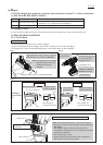
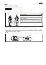
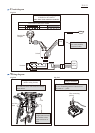
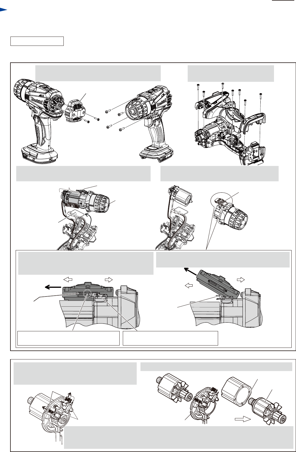
Fig. 8
1. Remove two 3x16 Tapping screws and Rear cover.
And remove four 4x18 Tapping screws.
After removing Drill chuck (Re: Figs. 1, 2, 3 and 4), disassemble Motor section and Gear assembly. (Figs. 8 and 9)
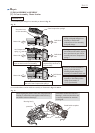
2. Remove Housing R, unscrewing
seven 3x16 Tapping screws.
3. Pull out Heat sink section, and remove Gear assembly
together with Motor section and Speed change lever.
4. Remove Speed change lever and Motor section
from Gear assembly.
Gear assembly
Speed change leverMotor section
Motor section
Rear cover
3x16 Tapping
screw (2 pcs.)
4x18 Tapping
screw (4 pcs.)
3x16 Tapping screw (7 pcs.)
Heat sink
section
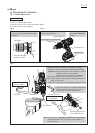
Speed change
lever assembly
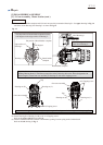
rear
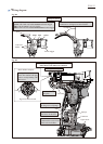
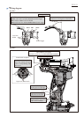
Compression
spring 4
front Compression spring 4 compressed
by the lever of Gear assembly
Drill chuck sideMotor side Drill chuck side
Motor side
5. Push Speed change lever assembly toward Motor side
until it stops to have space between the pin on the lever
of Gear assembly and rear Compression spring 4.
6. Lifting up Motor side of Speed change lever assembly,
pull it toward the direction designated with arrow.
Space between rear Compression spring 4
and the pin on the lever of Gear assembly.
Pin on
the lever of
Gear assembly
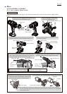
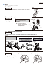
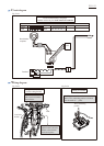
Fig. 9
Torsion spring
Carbon brush
Brush holder complete
Yoke unit
Armature
Note: Pay attention not to pinch your finger between Yoke unit and Armature when removing.
Do not scratch the copper wires of Armature. Yoke unit draws Armature by its considerable
strong magnet force.
5. Shift the tail of Torsion spring from top of Carbon
brush to the Notch of Brush holder. Carbon brush
gets free from the pressure of Torsion spring.
6. From Armature, pull off Brush holder complete and Yoke unit.