


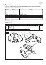
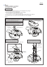
Fig. 10
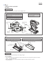
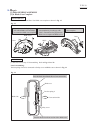
Fig. 11
[3] DISASSEMBLY/ASSEMBLY
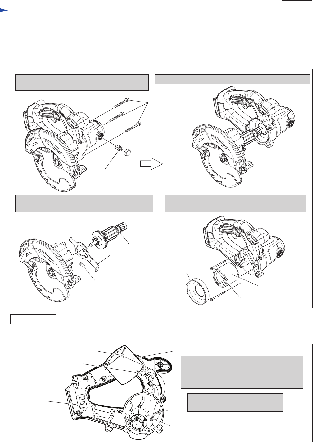
[3]-5. LED and Motor Section
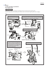
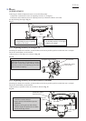
DISASSEMBLING
1. Remove Carbon brush and unscrew three M5x33
Pan head screws.
2. Separate Blade case section from Motor housing complete.
3. From Blade case section, Armature, Shaft lock and
Compression spring 6 are removed.
4. Disassemble Baffle plate and Yoke unit by unscrewing
two 4x65 Tapping screws.
(3) Armature and Yoke unit can be replaced as drawn in Fig. 10.
Carbon brush
M5x33 Pan
head screw
Armature
Compression
spring 6
Baffle plate
Yoke unit
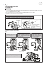
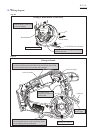
(1) Assemble Yoke unit to Motor housing complete as illustrated in Fig. 11.
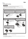
(2) Assemble Motor section by tasking the reverse step of Disassembling. Refer to Fig. 10.
4x65 Tapping screw
Shaft lock
Yoke unit
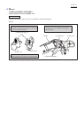
Note in Assembling:
Notch A and Notch B are reversible.
Note in Assembling:
Do not forget to assemble Shaft lock and Compression spring 6. Refer to the lower left drawing in Fig. 10.
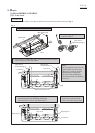
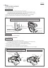
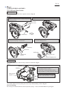
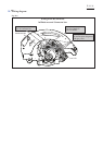
Insert Yoke unit into Motor housing complete,
while aligning Notch A to Rib A.
So, Yoke unit is exactly mounted to Motor
housing complete, by fitting Notch B to Rib B.
Motor housing
complete
ASSEMBLING
Rib A
Rib B
Notch A
Notch B
Repair
P 8/ 16