


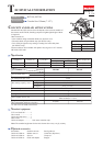
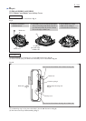

Wiring diagram
P 16/16
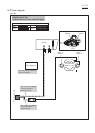
LED Light
circuit
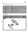
Fig. D-4
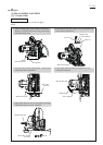
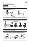
Fix Field lead wires
in these Lead wire
holders.
Switch
Field
Noise suppressor
(if used)
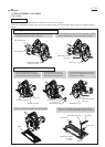
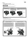
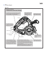
rib A
rib B
rib C rib D
Field lead wires must be
tight in Motor housing.
If Noise suppressor is used,
route Noise suppressor’s lead
wires between rib A and rib B.
Be careful not to put them on
Noise suppressor, ribs A and B.
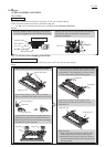
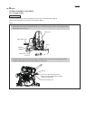
Be careful not to put
Lead wire (blue or white)
of Power supply cord
on Noise suppressor
after connecting
it to Terminal block.
Be careful not to put
Lead wires on the boss
and ribs A, B, C, D.
Field lead wires must be
tight in Motor housing.
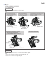
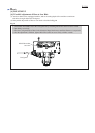
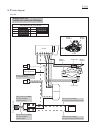
Strain relief
Terminal block
Set Terminal block in Handle section
with each terminal positioned as follows:
*On Strain relief side, the terminal with which
the Lead wire of Power supply cord is connected
must be positioned.
*On Field side, the terminal with which the Field
lead wire is connected must be positioned.
boss
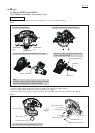
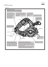
Route Field lead wires and
Lead wires of LED Light circuit
into Handle section through
this groove.
Fix Lead wires of
LED Light circuit
in this Lead wire
holder.
Fix Lead wires of
LED Light circuit
in these Lead wire
holders.
HS6101 & HS7101
(with Electric brake and LED light)