


P 4/16
Repair
[3] DISASSEMBLY/ASSEMBLY
[3] -1. Base
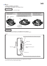
Fig. 3
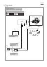
ASSEMBLING
ASSEMBLING, ADJUSTMENT
Base can be mounted to the machine by taking the reverse steps of Disassembling.
Note: Follow the important instructions described in Fig. 2A.
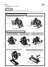
See Fig. 3 for Assembling and Adjustment of Lock lever for clamping Guide Rule.
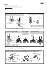
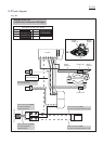
[3] -2. Lock Lever for clamping Guide Rule
Guide rule
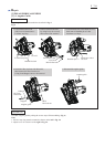
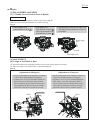
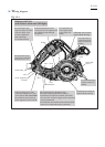
3. Applying the Torsion spring's long arm to the tab
of Base, put the Lock lever over M6x10 Hex bolt.
But do not push Lock lever down until you engage
it with the Hex bolt in the step 5.
4 . Lift up Lock lever so that its upper surface is flush
with that of M6x10 Hex bolt, then rotate Lock lever
independently. Then adjust the Lock lever so that
it can be locked in the position shown below.
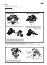
5 . Push Lock lever down until it engages with
M6x10 Hex bolt, then secure Lock lever with
Stop ring E-6.
6. Make sure that:
1) When Guide rule is clamped, Lock lever stops
in the same position as you set in the step 4.
2) With Guide rule removed, Lock lever returns to
its initial position smoothly and exactly from the
locking position..
M6x10 Hex bolt
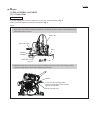
Mount Lock lever to Base and adjust its locking position when Guide rule attaching. (Fig. 3)
1. Fasten Guide rule to Base with M6x10 Hex bolt.
30 degrees
30 degrees
Stop ring E-6
Stop ring E-6
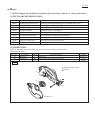
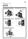
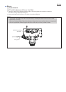
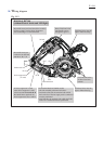
Be sure to mount E-8 Bow stop ring as shown below
for securely engaging Lever 45 with M6x20 Hex bolt.
Adjust Lever 45 so that it can be locked in the position
shown below when the machine’s cutting angle is
adjusted to 90 degrees.
30 degrees
Fig. 2A
Lever 45
M6x20 Hex bolt
Flat washer 6
E-8 Bow stop ring
Angular guide
Angular guide section,
viewed from top
Lever 45
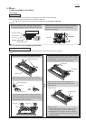
2. Insert Torsion spring 11 into Lock lever with its
short arm inserting in the square hole of Lock lever.
short arm
Torsion spring 11
Lock lever
tab
long arm long arm