


12
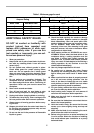
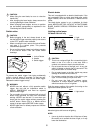
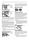
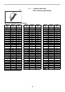
Vertical vise
The vertical vise can be installed in two positions on
either the left or right side of the guide fence. Insert the
vise rod into the hole in the guide fence and tighten the
screw on the back of the guide fence to secure the vise
rod.
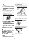
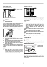
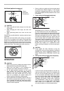
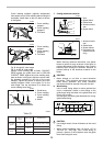
The vertical vise can also be secured to the rod on the
right side of the sub-fence R.
Position the vise arm according to the thickness and
shape of the workpiece and secure the vise arm by tight-
ening the screw. If the screw to secure the vise arm con-
tacts the guide fence, install the screw on the opposite
side of vise arm. Make sure that no part of the tool con-
tacts the vise when lowering the handle fully and pulling
or pushing the carriage all the way. If some part contacts
the vise, re-position the vise.
Press the workpiece flat against the guide fence and the
turn base. Position the workpiece at the desired cutting
position and secure it firmly by tightening the vise knob.
CAUTION:
• The workpiece must be secured firmly against the
turn base and guide fence with the vise during all
operations.
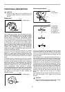
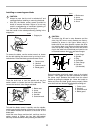
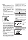
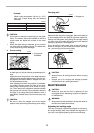
Horizontal vise (optional accessory)
The horizontal vise can be installed in two positions on
either the left or right side of the base. When performing
15° or greater miter cuts, install the horizontal vise on the
side opposite the direction in which the turn base is to be
turned.
By flipping the vise nut to the left, the vise is released,
and rapidly moves in and out. To grip the workpiece,
push the vise knob forward until the vise plate contacts
the workpiece and flip the vise nut to the right. Then turn
the vise knob clockwise to secure the workpiece.
The maximum width of workpiece which can be secured
by the horizontal vise is 200 mm (7-7/8”).
When installing the horizontal vise on the right side of the
base, also use the sub-fence R to secure the workpiece
more firmly. Refer to the “Sub-fence R” section described
on previously for installing the sub-fence R.
CAUTION:
• Always rotate the vise nut to the right fully when
securing the workpiece. Failure to do so may result
in insufficient securing of the workpiece. This could
cause the workpiece to be thrown, cause damage
to the blade or cause the loss of control, which can
result in PERSONAL INJURY.
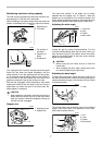
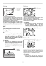
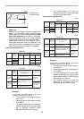
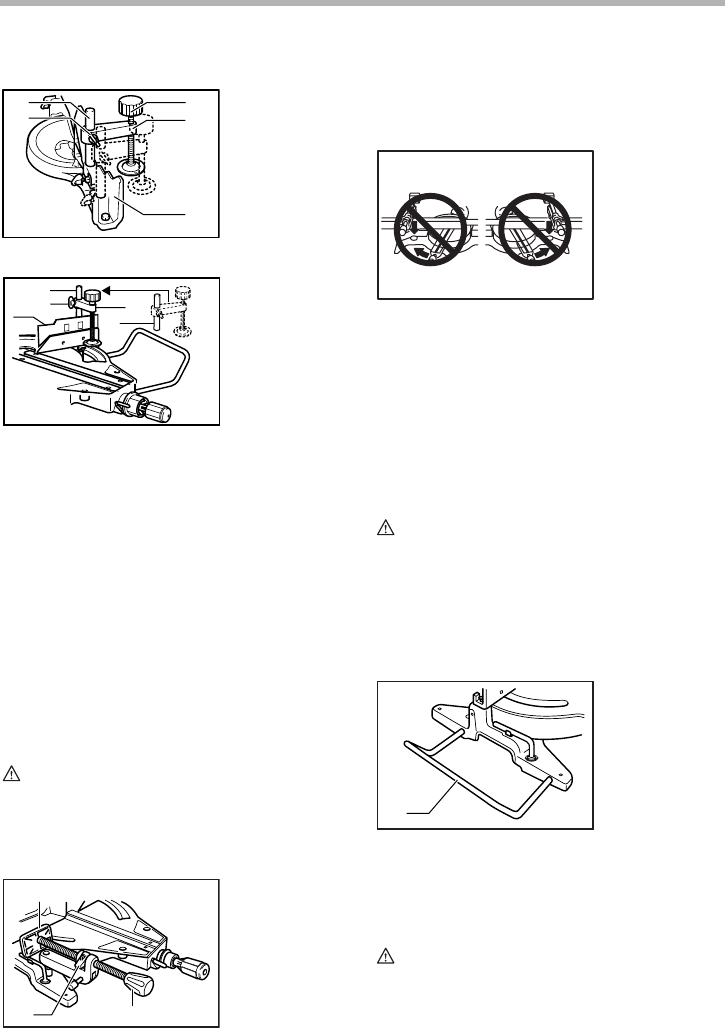
Holders
The holders can be installed on either side as a conve-
nient means of holding workpieces horizontally. Slip the
holder rods into the holes in the base and adjust their
length according to the workpiece to be held. Then
tighten the holders securely with the screws.
CAUTION:
• Always support long workpieces level with the top
surface of the turn base for accurate cuts and to
prevent dangerous loss of control of the tool.
1. Vise rod
2. Screw
3. Vise knob
4. Vise arm
5. Guide fence
1. Sub-fence R
2. Screw
3. Rod
4. Vise rod
5. Vise arm
1. Vise plate
2. Vise nut
3. Vise knob
1
2
3
4
5
005597
1
2
3
4
5
005688
1
2 3
001550
1. Holder
005232
1
001544