


15
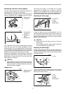
Measuring
Measure the wall length and adjust workpiece on
table to cut wall contact edge to desired length.
Always make sure that cut workpiece length at the
back of the workpiece is the same as wall length.
Adjust cut length for angle of cut. Always use sev-
eral pieces for test cuts to check the saw angles.
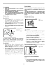
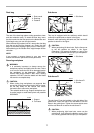
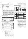
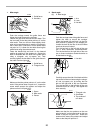
When cutting crown and cove moldings, set the
bevel angle and miter angle as indicated in the
table (A) and position the moldings on the top sur-
face of the saw base as indicated in the table (B).
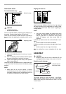
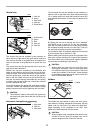
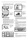
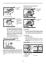
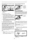
In the case of left bevel cut
Example:
In the case of cutting 52/38° type crown
molding for position (1) in Fig. A:
• Tilt and secure bevel angle setting to
33.9° LEFT.
• Adjust and secure miter angle setting to
31.6° RIGHT.
• Lay crown molding with its broad back
(hidden) surface down on the turn base
with its CEILING CONTACT EDGE
against the guide fence on the saw.
• The finished piece to be used will
always be on the LEFT side of the blade
after the cut has been made.
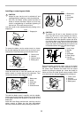
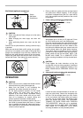
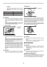
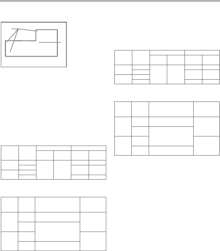
In the case of right bevel cut
Example:
In the case of cutting 52/38° type crown
molding for position (1) in Fig. A:
• Tilt and secure bevel angle setting to
33.9° RIGHT.
• Adjust and secure miter angle setting to
31.6° RIGHT.
• Lay crown molding with its broad back
(hidden) surface down on the turn base
with its WALL CONTACT EDGE against
the guide fence on the saw.
• The finished piece to be used will
always be on the RIGHT side of the
blade after the cut has been made.
1. Inside corner
2. Outside corner
2
(1)
(2)
(1)
(2)
(2)
(1)
(2)
(1)
(1)
(2)
(3)
(4)
1
001557
(1)
(2)
(3)
(4)
Molding
position in
Fig. A
Bevel angle Miter angle
For outside
corner
For inside
corner
52/38˚ type
45˚ type
Right 31.6˚
45˚ type
Left 33.9˚ Left 30˚
52/38˚ type
Left 31.6˚
Right 31.6˚
Left 35.3˚
Right 35.3˚
Right 35.3˚
Table (A)
006361
Molding
position in
Fig. A
Molding edge against
guide fence
Finished piece
(1)
Ceiling contact edge should
be against guide fence.
(2)
(3)
(4)
Ceiling contact edge should
be against guide fence.
For
outside
corner
Finished piece
will be on the
Left side of
blade.
Finished piece
will be on the
Right side of
blade.
For inside
corner
Wall contact edge should be
against guide fence.
Table (B)
006362
(1)
(2)
(3)
(4)
Molding
position in
Fig. A
Bevel angle Miter angle
For outside
corner
For inside
corner
52/38˚ type
45˚ type
Right 31.6˚
45˚ type
Right 33.9˚ Right 30˚
52/38˚ type
Left 31.6˚
Right 31.6˚
Left 35.3˚
Right 35.3˚
Right 35.3˚
Table (A)
006363
Molding
position in
Fig. A
Molding edge against
guide fence
Finished piece
(1)
Ceiling contact edge should
be against guide fence.
(2)
(3)
(4)
For
outside
corner
Finished piece
will be on the
Left side of
blade.
Finished piece
will be on the
Right side of
blade.
For inside
corner
Wall contact edge should be
against guide fence.
Table (B)
Wall contact edge should be
against guide fence.
006364