


21
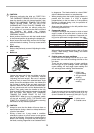
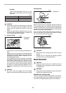
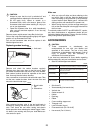
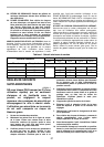
(2) 45° bevel angle
Adjust the 45° bevel angle only after perform-
ing 0° bevel angle adjustment. To adjust left
45° bevel angle, loosen the lever and tilt the
blade to the left fully. Make sure that the
pointer on the arm points to 45° on the bevel
scale on the arm holder. If the pointer does
not point to 45°, turn the left 45° bevel angle
adjusting bolt on the side of the arm holder
until the pointer points to 45°.
To adjust right 45° bevel angle, perform the
same procedure described above.
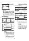
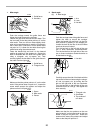
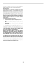
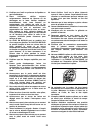
Adjusting for smooth beveling action
The hex lock nut holding together the arm and arm
holder has been factory adjusted to assure smooth bev-
eling action and to guarantee precise cutting. Do not
tamper with it. Should looseness develop at the arm and
arm holder connection, tighten the hex lock nut using a
wrench.
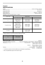
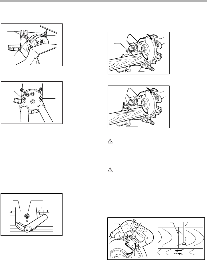
Adjusting the position of laser line
For model LS1214L only
WARNING:
• As the tool is plugged when adjusting the position
of laser line, take a full caution especially at switch
action. Pulling the switch trigger accidentally cause
an accidental start of the tool and personal injury.
CAUTION:
• LASER RADIATION
Do not stare into beam.
• Never apply a blow or impact to the tool. A blow or
impact causes the incorrect position of laser line,
damage to the laser beam emitting part or a short
life of the tool.
When adjusting the laser line appears on the left side
of the saw blade
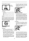
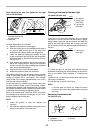
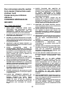
1. Bevel scale
2. Screws
3. Pointers
1. Arm holder
2. Right 45° bevel
angle adjusting
bolt
3. Left 45° bevel
angle adjusting
bolt
1. Arm
2. Hex lock nut
2
1
3
3
001572
1
3
2
001573
1
2
004860
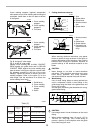
1. Workpiece
2. Cutting line
3. Holder
1. Vertical vise
2. Holder
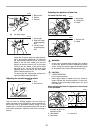
1. Screw to change the
movable range of the
adjusting screw
2. Adjusting screw
3. Hex Wrench 4. Laser line
5. Saw blade
1
2
3
006342
1
2
006343
1
2
3
4
5
006345