


7
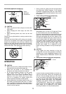
Maintaining maximum cutting capacity
This tool is factory adjusted to provide the maximum cut-
ting capacity for a 305 mm (12”) saw blade.
When installing a new blade, always check the lower limit
position of the blade and if necessary, adjust it as follows:
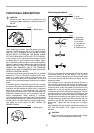
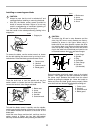
First, unplug the tool. Push the carriage toward the guide
fence fully and lower the handle completely. Use the
socket wrench to turn the adjusting bolt until the periph-
ery of the blade extends slightly below the top surface of
the turn base at the point where the front face of the
guide fence meets the top surface of the turn base.
With the tool unplugged, rotate the blade by hand while
holding the handle all the way down to be sure that the
blade does not contact any part of the lower base. Re-
adjust slightly, if necessary.
CAUTION:
• After installing a new blade, always be sure that the
blade does not contact any part of the lower base
when the handle is lowered completely. Always do
this with the tool unplugged.
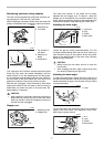
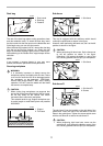
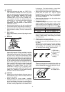
Stopper arm
The lower limit position of the blade can be easily
adjusted with the stopper arm. To adjust it, rotate the
stopper arm in the direction of the arrow as shown in the
figure. Adjust the adjusting screw so that the blade stops
at the desired position when lowering the handle fully.
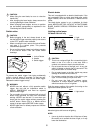
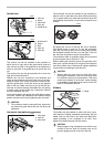
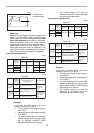
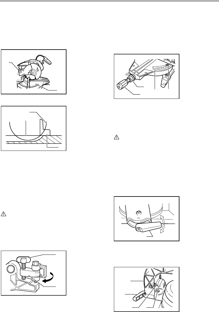
Adjusting the miter angle
Loosen the grip by turning counterclockwise. Turn the
turn base while pressing down the lock lever. When you
have moved the grip to the position where the pointer
points to the desired angle on the miter scale, securely
tighten the grip clockwise.
CAUTION:
• When turning the turn base, be sure to raise the
handle fully.
• After changing the miter angle, always secure the
turn base by tightening the grip firmly.
Adjusting the bevel angle
To adjust the bevel angle, loosen the lever at the rear of
the tool counterclockwise. Unlock the arm by pushing the
handle somewhat strongly in the direction that you intend
to tilt the saw blade.
Tilt the saw blade until the pointer points to the desired
angle on the bevel scale. Then tighten the lever clock-
wise firmly to secure the arm.
1. Adjusting bolt
2. Turn base
1. Top surface of
turn base
2. Periphery of
blade
3. Guide fence
1. Adjusting screw
2. Stopper arm
1
2
004066
2
1
3
001540
1
2
001562
1. Lock lever
2. Grip
3. Pointer
4. Miter scale
1. Lever
1. Arm
2. Lever
3. Pointer
4. Bevel scale
1
2
4
3
001541
1
004056
1
2
3 4
001543