


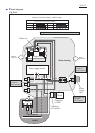
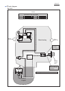

Wiring diagram
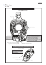
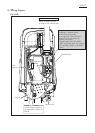
RP1801 with electric Brake
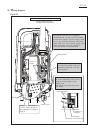
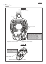
Grip R
Lead Wire
Holder
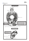
When putting Lead wires for
connecting to Terminal block,
into this Lead wire holder,
Noise suppressor’s thin Lead wire
(white) has to be put under the
following Lead wires.
* Support unit’s lead wire (black)
* Thick Connecting lead wire (purple)
for connecting Switch to Terminal
block
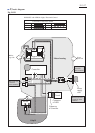
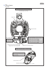
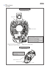
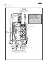
Switch lever
Terminal block
Connecting lad wires
(yellow, orange purple) to
be connected to Switch in
Grip R
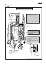
Fig. D-2D
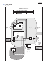
Noise
suppressor
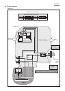
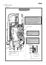
Wiring in Motor housing
on Grip R side (Switch side)
P 20/ 27