Repair
CAUTION: Remove the bit from the machine for safety before repair/ maintenance
in accordance with the instruction manual!
[1] NECESSARY REPAIRING TOOLS
[2] LUBRICATIONS
[3] DISASSEMBLY/ASSEMBLY
[3]-1. Base complete
Fig. 1
Fig. 2
Code No. Description Use for
1R030 Bearing setting pipe 25-17.2 Supporting Pin 6 when assembling shaft lock mechanism
1R268 Spring pin extractor 3 Removing Pin 6 of shaft lock mechanism
1R269 Bearing extractor Removing Ball bearing 629DDW
Item No.
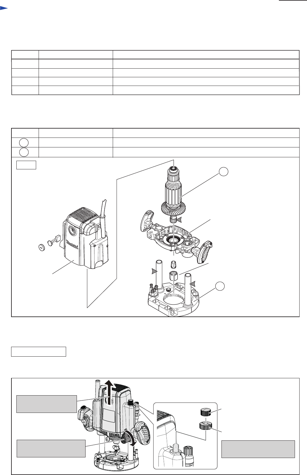
Apply lubricant “VG100” to the following portions designated with the gray triangle to protect parts
and product from unusual abrasion.
Description
Armature
Portion to lubricate
DISASSEMBLING
(1) Separate Base section from Motor section as illustrated in Figs. 2 and 3.
3. Remove M10 Thumb nut
and M10 Nylon nut
24
Motor bracket complete
Collet nut
Motor housing
85
24
85 Base complete
Threaded portion for removing Collet nut smoothly
Pipe 20 for making plunging action smooth
M10 Thumb nut
M10 Nylon nut
1R041 Vise plate Protecting Armature when holding in vise
1. Set Motor section to
the upper position.
2. Lock Motor section
by turning Lock lever.
P 3/ 27


