


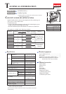
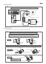
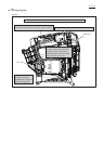
Circuit diagram
Wiring diagram
Orange
Line filter
Housing L side
Handle side Handle side
Housing
L side
Housing
L side
Housing L side
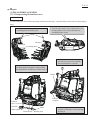
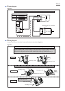
Connect Flag terminals of the Lead wires to terminals of DC motor and route the Lead wires through Line filter.
Color index of lead wires' sheath
Black
Red
Switch
DC Motor
Terminal
Switch
Line Filter
Red dot mark for + terminal
DC Motor
Terminal
Red dot mark
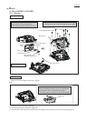
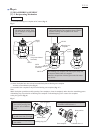
Face the terminals of M1, M2 to Housing L side and connect Lead wires (orange) and (black)
with terminals of Switch correctly in order to set Switch exactly in the Housing L.
Note; Do not overlap the Lead wires on the Switch body where they contact to Housing L.
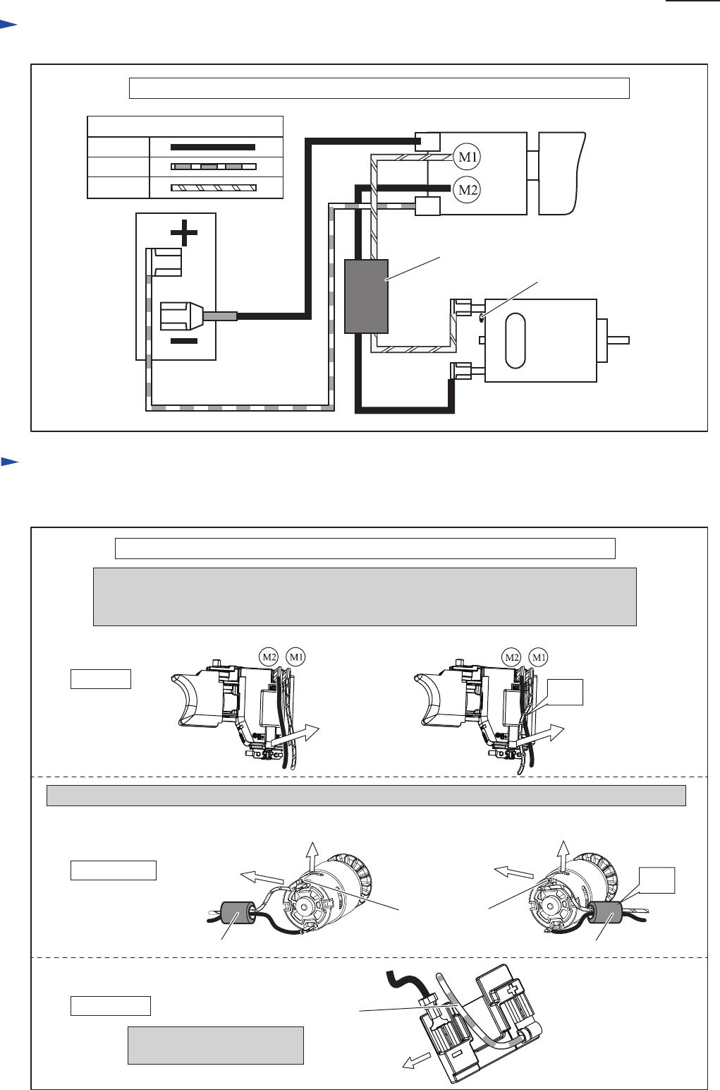
For the countries where the regulations for radio interference suppression are required.
For the countries where the regulations for radio interference suppression are required.
Fig. D-1
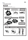
Fig. D-2
Housing L side
Line filter
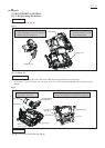
Connect Lead wires to Switch, DC motor and Terminal as described in Fig. D-2.
Lead wire (red)
Connect the Lead wire (red)
at described direction.
NG
NG
P 8/ 11