1.3
MIG/MAG 140/160
x Switch the unit off for longer work breaks.
Unplug when work is completed and before relo-
cating the unit. In case of accidents separate the
welding power source at once from the power
supply.
General Machine Description
The MIG/MAG welding machine consists of a trans-
former (static characteristic curve), a series-con-
nected silicon rectifier, a welding circuit choke, and
a wire feed unit.
The welding machine is suitable for the welding of
different electrode wires (e.g. steel, see "Technical
Specifications") under a shielding gas cover (CO2,
mixed gas and argon).
The machine is fan cooled and has an overload pro-
tection.
Symbols Used
Danger!
Disregard of the following warnings
could cause serious personal injury
or material damage.
Read operating instructions before
initial operation
Wire feed speed
Do not use in rain.
Welding machine suitable for welding in
environments with an increased electri-
cal hazard.
Excess temperaturer
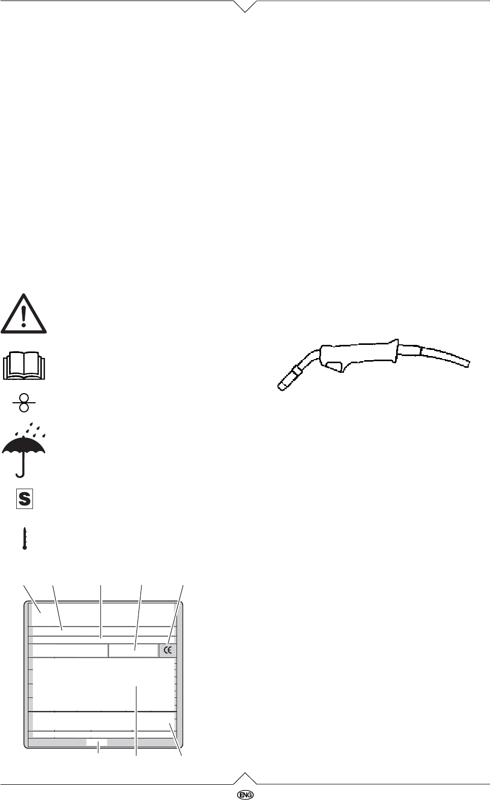
Information on the name plate:
Commissioning
Taking out of enclosed parts
All enclosed parts are inside the wire feed compart-
ment and can be taken out after the wire feed com-
partment cover is removed..
Installation Conditions
x The protective gas welding unit must be
installed in a dry environment with sufficient
room for cooling.
x If the unit is placed on an inclined surface it must
be secured against falling: place the unit on a
suitable level support surface.
x The unit is designed for use in covered areas.
Welding outside in the rain is not permitted.
Mains connection
x Check to see that mains voltage matches the
voltage shown on the machine's rating plate.
x Set welding step switch to "0" before plugging
in.
Shielding gas cylinder connection
x Place gas cylinder onto the welding machine's
cylinder rack and secure with the chain to the
cylinder holder at the rear of the unit. Take off
the cylinder cap and open cylinder valve briefly,
facing away from your body.
x Screw pressure reducer to the gas cylinder
valve. Run gas hose from pressure reducer to
gas inlet port of the unit.
x Recommended gas flow rate in draft-free
rooms: 5-10 l/min.
78910
1213
6
11
6 Manufacturer
7 Machine designation
8 Serial number
9 Standard information – This machine meets
the requirements of the standards mentioned
10 CE mark – This machine conforms to EC
directives as per declaration of conformity
11 Waste disposal symbol – the machine can be
disposed of through the manufacturer
12 Electrical performance data
13 Date of manufacture


