21
ENGLISH
Read instructions.
Do not reach into the run-
ning saw blade.
Wear safety goggles and
hearing protection.
Do not operate tool in moist
or wet environment.
Danger!
Avoid direct eye contact
with the laser beam.
Do not carry tool at
the handle; the han-
dle is not designed to
bear the weight of the
tool.
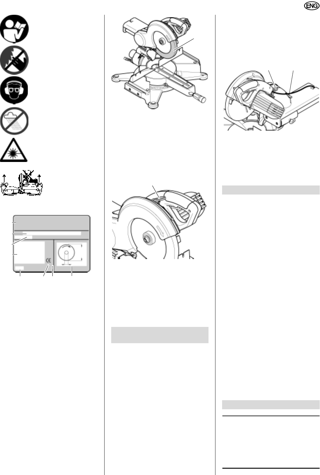
Information on the nameplate:
3.4 Safety Devices
Retractable blade guard
The retractable blade guard (39) pro-
tects against unintentional contact with
the saw blade, and from chips flying
about.
Both segments of the retractable blade
guard must always return automatically
into their starting position: when the saw-
head is lifted up, the sawblade must be
covered all around.
Safety lock
The safety lock (40) prevents the retract-
able blade guard from unintentional
opening.
For sawing the safety lock is pressed
down. Only then can the sawhead be
lowered, opening the retractable blade
guard.
After the cut – when the sawhead is
back in its upper starting position – the
retractable blade guard is automatically
locked again.
A
Caution!
Do not carry tool at the handle;
the handle is not designed to bear the
weight of the tool. To carry, hold the
tool at both sides of the base.
Installation
1. Lift the tool out of the box with the
help of another person.
Keep the packing for future use, or
separate by material and dispose of
in an environmentally friendly man-
ner.
2. Place tool on a suitable base:
− All four feet must firmly rest on
the base.
− The ideal height of the base is
800 mm.
− The saw must stand securely,
even when cutting larger work-
pieces.
3. Push the sawhead slightly down and
pull the transport locking pin (42) out
– the sawhead can then be fully
lifted.
Transport
1. If necessary, adjust the cutting
depth limiter (41) to the maximum
depth of cut.
2. Lower the sawhead and push the
transport locking pin (42) in.
− 0° to 47° cutting angle range left and
right, with nine positive stops for
mitre cuts.
− 0° to 45° cutting angle range for
bevel cuts.
− Integrated cutting depth stop for
grooving.
− Perfect for mobile use because of its
low weight and small dimensions.
− Precise and sturdy die-cast alumin-
ium construction.
− TCT saw blade.
− Unproblematic saw blade change by
saw blade lock; no dismounting of
the retractable blade guard required.
− Maximum dept of cut 60 mm.
− Track arm provides for up to 255
mm cutting width.
− Work support with support and stock
stop to cut longer workpieces safely.
− Work clamp to hold workpieces
securely.
− Chip bag for simple and effective
collection of chips.
− Flange laser for exact alignment of
markings with the cutting line.
3
Note:
In this chapter the essential oper-
ating elements of the machine are intro-
duced.
The proper use of the saw is described
in chapter "Operation". Read this chap-
ter before using the saw for the first time.
(30) Manufacturer
(31) Serial number
(32) Machine designation
(33) Motor specifications (see also
“Technical Specifications”)
(34) Date of manufacture
(35) CE-mark – This machine con-
forms to the EC directives as per
Declaration of Conformity
(36) Waste disposal symbol –
Machine can be disposed of by
returning it to the manufacturer
(37) Dimensions of permissible saw
blades
31
32
33
34 35 36
30
37
4. Installation and Trans-
port
39
40
5. Special Product Features
6. Machine Details
41 42


