


OM-1500-14 Page 25
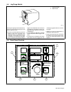
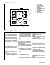
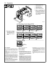
5-12. Auxiliary Menus
Program
Start
Crater
Pre/Postflow
Trigger Hold
Adjust
Volts Time (sec)
Wire Speed Amps
Sequence Setup
Dual Schedule
3
4
2
9
8
1
5
7
6
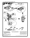
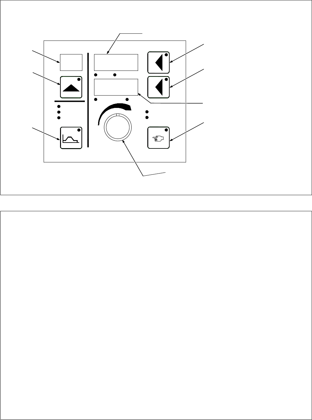
1 Program Display
2 Program Push Button
3 Sequence Push Button
4 Upper Display
5 Upper Display Push Button
6 Lower Display
7 Lower Display Push Button
8 Adjust Control
9 Setup Push Button
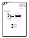
Reset To Factory Settings
A reset menu is displayed if the following four
push buttons are pressed simultaneously:
Program, Sequence, upper display, and Set-
up. The upper display indicates “WIPE” . The
lower display indicates “OFF”. The lower push
button is active indicating that the Adjust con-
trol can be used to change the unit to “WIPE
ON”. When “WIPE ON” is set, if the original
four push buttons are simultaneously pressed
a second time, the unit will reset all settings to
factory default except the arc time and arc
cycle counts. If a reset is not desired, set the
display to “WIPE OFF” and simultaneously
press the Program, Sequence, upper display,
and Setup push buttons to exit the reset menu.
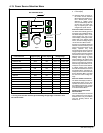
Auxiliary Menu
• An auxiliary menu is provided if both the Se-
quence and Setup push buttons are pressed
simultaneously. The Setup push button and
sequence push button LEDS flash when the
auxiliary menu is displayed.
Pushing the Setup push button will step
through the menu. Pushing the sequence
push button will step through the menu in re-
verse.
. The auxiliary menu may be exited at any
time by pressing both the Sequence push
button and the Setup push buttons simul-
taneously.
V-Min And V-Max
• If the Setup push button is pressed, the unit
allows the setting of the manual override
power source min and max voltage preset
range. The minimum voltage is displayed in
the upper display and the lower display indi-
cates “VMIN”. When the Setup push button
is pressed the unit displays the maximum
voltage setting of the welding power source.
The maximum voltage is displayed in the up-
per display and the lower display indicates
“VMAX”.
In both cases, the Adjust control is used to
specify the minimum and maximum voltage
settings of the welding power source. The set-
tings correspond to arc voltage obtained at
minimum command and arc voltage obtained
at maximum command.
This method of setting “VMIN” and “VMAX”
may be used if the power source being used
is not listed in the Power Source Selection
Menu.
. If a default power source has already been
selected with the Power Source Selection
menu, setting “VMIN” and “VMAX” will
override the default power source set-
tings.
. The power source selection menu must
be set to “OFF” when overriding the de-
fault “VMIN” or “VMAX” settings.
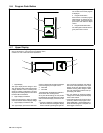
Power Source Selection Menu
• If the Setup push button is pressed, the unit
allows the Power Source Selection menu to
be disabled or enabled.
The upper display shows “PSS”. Lower dis-
play shows “On” or “Off”. The Adjust Control is
used to select either “On” or “Off”.
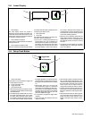
Arc Time
• If the Setup push button is pressed, the unit
displays arc time in hours.
Arc time is indicated by the Program display
showing “HR”. Arc time is shown in the lower
display.
Cycles
• If the Setup push button is pressed, the unit
displays the number of cycles.
Arc cycles are indicated by the Program dis-
play showing “CL”. The arc cycle count is
shown in the lower display.
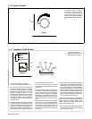
Run-In
• If the Setup button is pressed, the unit allows
setting the run-in modes. The run-in modes
are program specific. Each program may be
set to its own run-in mode.
The upper display indicates “RUNI”. The
lower display indicates “AUTO”, meaning the
factory set automatic run-in speed is se-
lected.
Pressing the lower display button allows a
manual setting the run-in wire speed. Speed
may be adjusted from 10% to 100% of weld
wire speed.
Pressing the lower display button allows dis-
abling of the run-in feature. When the lower
display indicates “OFF” run-in is disabled.
5-12 Auxiliary Menus (Continued)