


OM-1500-14 Page 29
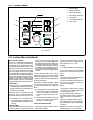
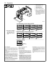
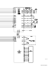
7-2. Diagnostics
803 063-A
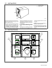
1 LED3 On Right Side Motor
Control Board PC1
2 LED3 On Left Side Motor
Control Board PC101
3 LED4 On Dual Board PC70
. There is a two-position DIP
switch S1 located on motor con-
trol boards PC1 and PC101.
These switches are factory-set
in the off position and must re-
main in that position for the unit to
operate correctly.
Error Indications
Error conditions are indicated by LED3 on
PC1, PC101, and LED4 on PC70. To view
LEDs, turn Off unit, remove wrapper, and turn
unit On.
The LED blinks in a 2.5 second cycle. The
number of blinks in this period indicates the
type of error.
The priority of the errors is related to the num-
ber of blinks indicating the error. The more
blinks, the more severe the error (motor error
is top priority). A higher priority error overrides
a lower one (if a motor error and a commu-
nication error existed, the light would blink four
times for the motor error).
Since blink On time and blink Off time are
equal in a four-blink cycle, the four−blink se-
quence appears as a constant blink.
1 blink = Communication Error
2 blinks = Trigger Error
3 blinks = Tach Error
4 blinks = Motor Error
• The communication error occurs 2.5 sec-
onds after a loss of communication be-
tween the motor and the Front Panel board
or Dual board. The user may continue to
weld with this error.
• The trigger error occurs if the user has the
trigger held for more than two minutes with-
out striking an arc (providing current over-
ride is not enabled), or if the user holds the
trigger past the postflow phase in a timed
weld. This error also occurs if the trigger is
held when the feeder is powered up. The er-
ror may be cleared by releasing the trigger.
• The tach error occurs 2 seconds after the
loss of tachometer feedback. The user may
continue to weld with this error. The motor
speed is regulated through the monitoring of
voltage and current.
• The motor error indicates that the motor
has been drawing too much current for too
long.
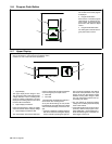
ERR
COM1
ERR
TRG1
ERR
TCH1
ERR
MTR1
. Note: The error messages
are shown on the upper
and lower displays to indi-
cate specific errors. Ex-
planations are in the text
below:
Indicates a com-
munication error.
Indicates a trigger
error.
Indicates a
tachometer error.
Indicates a motor
error.
Left Side Motor Control Board PC101
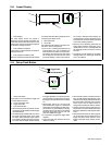
ERR
COM2
ERR
TRG2
ERR
TCH2
ERR
MTR2
Indicates a com-
munication error.
Indicates a trigger
error.
Indicates a
tachometer error.
Indicates a motor
error.
Right Side Motor Control Board PC1
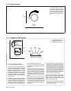
ERR
COM3
Indicates a
communication
error.
Dual Board PC70
2
1
3