


OM-1500-14 Page 26
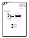
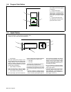
Burnback
• If the Setup push button is pressed, the unit
allows burnback time to be set.
Burnback time and voltage can be specified
when the lower display indicates “BURN” and
the upper display indicates the burnback time
or voltage. The Adjust control is used to set the
desired burnback time or voltage. Burnback
settings, like run-in settings, are program spe-
cific. The active program is displayed in the
Program display and can be adjusted (see
Section 5-6).
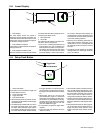
Trigger Hold Setup
• If the Setup push button is pressed, the unit
allows trigger hold delay time to be set.
Trigger hold delay time is indicated by ”HOLD”
in the lower display and the hold delay time in
the upper display. The adjust control can be
used to specify a new delay time for trigger
hold. Trigger hold delay time is the minimum
amount of time the trigger must be held for trig-
ger hold to work when the trigger is released
(the trigger hold function must be on). For ex-
ample, if a trigger hold delay time of 2.0 sec-
onds is defined, the operator must hold the
trigger for at least 2 seconds before releasing
it in order for the trigger hold function to work.
Once the trigger hold function is in effect, the
wire feeder will stay On until the trigger is
pressed and released again.
• There is an additional function built in called
”maximum trigger hold time” which is the
maximum length of time the trigger can be
held and the trigger hold function still work
when the trigger is released (the trigger hold
function must be on). The maximum trigger
hold time is set at 4.0 seconds after the trig-
ger hold delay time. For example, if a trigger
hold delay time of 2.0 seconds is defined,
and the operator held the trigger in for more
than 6.0 seconds, the trigger hold function
would not be in effect and the wire feeder
would stop when the trigger is released.
• When the Setup push button is pressed
again, the menu repeats to the first menu
selection of run-in wire speed selection.
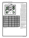
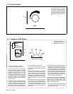
Trigger Program Select
• If the Setup push button is pressed, the unit
allows Trigger Program Select or Trigger
Dual Schedule to be enabled or disabled.
The upper display shows “TSEL”. Lower dis-
play shows “OFF” or “PROG” or “DUAL”. The
Adjust Control is used to select “OFF” or
“PROG” or “DUAL”.
Trigger Program Select (PROG) allows the
operator to select programs during preflow by
clicking the trigger (pulling and releasing the
trigger in a maximum of 0.2 seconds). The
feeder will switch between any programs that
have a minimum of 0.2 seconds of preflow time
set in the weld sequence. Any combination of
programs may be used. Trigger Program Se-
lect cannot be used while welding or with Dual
Schedule.
(Example: If programs 1 and 3 have a mini-
mum of 0.2 seconds of preflow time, clicking
the trigger will toggle between programs 1 and
3).
Trigger Dual Schedule Select (DUAL) allows
the operator to switch between paired sched-
ules (programs 1−2, 3−4, 5−6, or 7−8) with the
gun trigger, but only while welding. This fea-
ture cannot be used with Trigger Hold or Dual
Schedule. To end the weld, the trigger must be
released for 0.4 seconds.
(Example: when welding with this feature en-
abled in program 1, if you release, re-trigger,
and hold again within <0.4 seconds, the active
program will switch to program 2. If the pre-
vious sequence is repeated the active pro-
gram will switch back to program 1. This cycle
can be repeated for the entire weld).
Process Select
Process selection indicated by ”PROS” in the
upper display is set to either ”VOLT” or ”TRIM”
in the lower display. Each program can be se-
lected be be a MIG program indicated by
”VOLT” or a pulsing program indicated by
”TRIM”.
Range Locks
Range locks are indicated by “LOCK” in the
upper display for wire speed or “LOCK” in the
lower display for voltage range. In a MIG pro-
gram, the voltage range lock ranges from 0 to
10 volts. In a pulse program, the trim range
lock ranges from 0 to 100. The wire feed speed
range lock ranges from 0 to 250 ipm. Locks are
program dependent and wire speed is inde-
pendent from voltage or trim.
Wire Feed Speed Units
Wire feed speed setting indicated by “WFS” in
the upper display is set to “IPM” inches−per−
minute or ”MPM” meters−per−minute. This
setting is independent of the program se-
lected.
OPT1
• If the Setup push button is pressed, the unit
allows OPT1 to be disabled or enabled.
The upper display shows “OPT1”. Lower dis-
play shows “On” or “Off”. The Adjust Control is
used to select either “On” or “Off”.
“OPT1” is used by the Water Flow Shutdown
Option to stop the weld sequence if water flow
to a water cooled gun is interrupted. A closed
set of contacts between pins 1 and 2 of RC26
on Interface Board (PC20) will allow feeder to
operate normally. Opening the contacts will
stop the weld sequence and display “ERR” in
the upper display and “OPT1” in the lower dis-
play.
OPT2
• If the Setup push button is pressed, the unit
allows OPT2 to be disabled or enabled.
The upper display shows “OPT2”. Lower dis-
play shows “On” or “Off”. The Adjust Control is
used to select either “On” or “Off”.
“OPT2” is a second input that may be used
with an external device, such as a gas flow
switch, to end the weld sequence. The gas
flow switch may be used to stop the weld se-
quence if shielding gas flow to the gun is inter-
rupted. A closed set of contacts between pins
1 and 2 of RC24 on Interface Board (PC20) will
allow feeder to operate normally. Opening the
contacts will stop the weld sequence and dis-
play “ERR” in the upper display and “OPT2” in
the lower display.
Display Hold
Display hold indicated by ”DISP” in the upper
display is set to “OFF” or “HOLD” in the lower
display. When ”HOLD” is selected, the unit will
hold the last weld information for 5 seconds fol-
lowing weld termination. If any front panel
push button is pressed, or if the Adjust control
is activated, the display hold feature is termi-
nated.
Software Revision Level
• If the Setup push button is pressed, the unit
displays the software version being used by
the interface PCB (PC20).
• When the Setup button is pressed again, the
menu repeats.
Code
Upon leaving the auxiliary menu, the user is
asked if a password code indicated by
“CODE” in the top display should be activated.
By default the code is off, indicated by “OFF”
in the lower display. The user may enter a nu-
merical password between 0 and 999 by turn-
ing the Adjust control. When the user re−en-
ters the auxiliary menu, the password code
must be selected to gain access to the auxilia-
ry menu. A failed attempt return the user to the
weld screen and a counter is incremented. A
counter in the program display shows the
number of incorrect attempts. The user has
five attempts to enter the correct password
code before being locked out of the auxiliary
menu, indicated by “LOCK” in the lower dis-
play . The power may be cycled to continue
welding but the user will remained locked out
of the auxiliary menu. Pressing the Program,
Sequence, upper display, and Set−up push
buttons simultaneously, the counter can be re-
set in the weld screen. Resetting the counter
is indicated by “CODE” in the upper display
and “RSET” in the lower display. Pressing the
Program, Sequence, upper display, and Set−
up push buttons simultaneously again will al-
low the user to reset the unit to the factory de-
faults, indicated by “WIPE” in the upper dis-
play. Resetting the unit will also turn off the
password code feature.
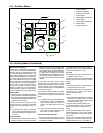
5-12 Auxiliary Menus (Continued)