


OM-210 540 Page 26
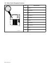
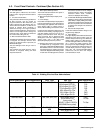
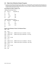
Table 4-2. Robot Abbreviations
Manufacturer
Robot Abbreviation
ABB ABB
Fanuc FANU
Daihen DAHN
Kawasaki KAWA
Kuka KUKA
Comau COMU
Hitachi HCHI
Nachi NCHI
Panasonic PANA
Motorman MOTO
Robot Adapter DTEC
Detect Disabled OFF
None Robt DTEC
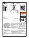
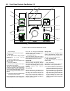
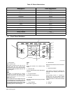
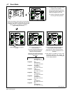
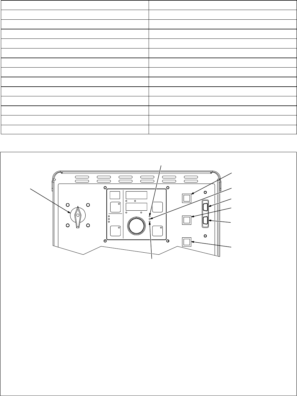
4-4. Front Panel Switches
1
2
3
4
Ref. 803 246-B
1 Power Switch
Turns unit On or Off.
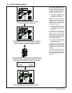
The power-up sequence may last up to 30
seconds before the unit is ready to weld.
During power-up, the front panel will display
messages indicating the status of the unit. The
first message is:
NET
WAIT
NET WAIT is an abbreviation for ”network
updating” and means the internal control
network is powering up. The next message is
XXXX (Robot Type)
XXXX identifies the robot adapter being used
as identified by the unit (see Table 4-2 for a list
of robot adapters that could be displayed). To
ensure proper operation of the system, verify
the robot displayed corresponds to the actual
robot being used. The final message is
AUTO
450
AUTO 450 indicates the software being
loaded.
2 Contactor LED
Contactor LED illuminates when weld output is
energized.
3 Purge Push Button
Press button to purge gas line.
4 Gas LED
Gas LED illuminates when Purge push button
is pressed.
5 Jog Push Button
Press button to jog wire.
6 Wirefeed LED
Wirefeed LED illuminates when wire feeds or
retracts.
7 Retract Push Button
Press button to retract wire. Wirefeed LED
illuminates when Retract push button is
pressed.
Auto-Threading feature is activated by
pressing the Jog and Retract buttons
simultaneously. Pressing the Jog, Purge, or
trigger switch will turn off the Auto-Threading
feature.
8 PDA Port
9 PC Port
6
7
5
8
9