


OM-210 540 Page 45
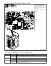
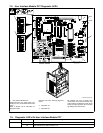
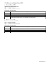
7-12. Network And Module Status LED’s
A. Network Status LED’s
The following are network status LED’s:
LED1 on the UIM circuit board
LED4 on the WFM and PCM circuit boards
LED30 on the AIM circuit board.
Status Diagnosis
Off The circuit board is not on-line with the network or there is no power applied to the circuit board.
Green The circuit board is operating normally and the on-line connection is made with the network.
Flashing Green The circuit board is waiting for an on-line connection to be made with the network.
Red The circuit board has encountered a communication link failure with the network. Check DeviceNet cable connections. Verify
dip switch positions according to Sections 1-2 and 1-3. Replace circuit board if necessary.
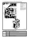
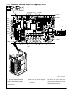
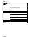
B. Module Status LED’s
The following are module status LED’s:
LED2 on the UIM circuit board
LED3 on the WFM and PCM circuit boards
LED31 on the AIM circuit board.
Status Diagnosis
Off There is no power applied to the circuit board or the board software is not executing its functions.
Green The circuit board is operating normally.
Flashing Red The circuit board has encountered a recoverable fault. Wait or cycle power to clear fault.
Red The circuit board has encountered an unrecoverable fault.