


OM-173 413 Page 22
SECTION 5 – OPERATING THE WELDING GENERATOR
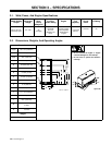
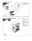
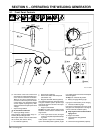
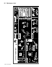
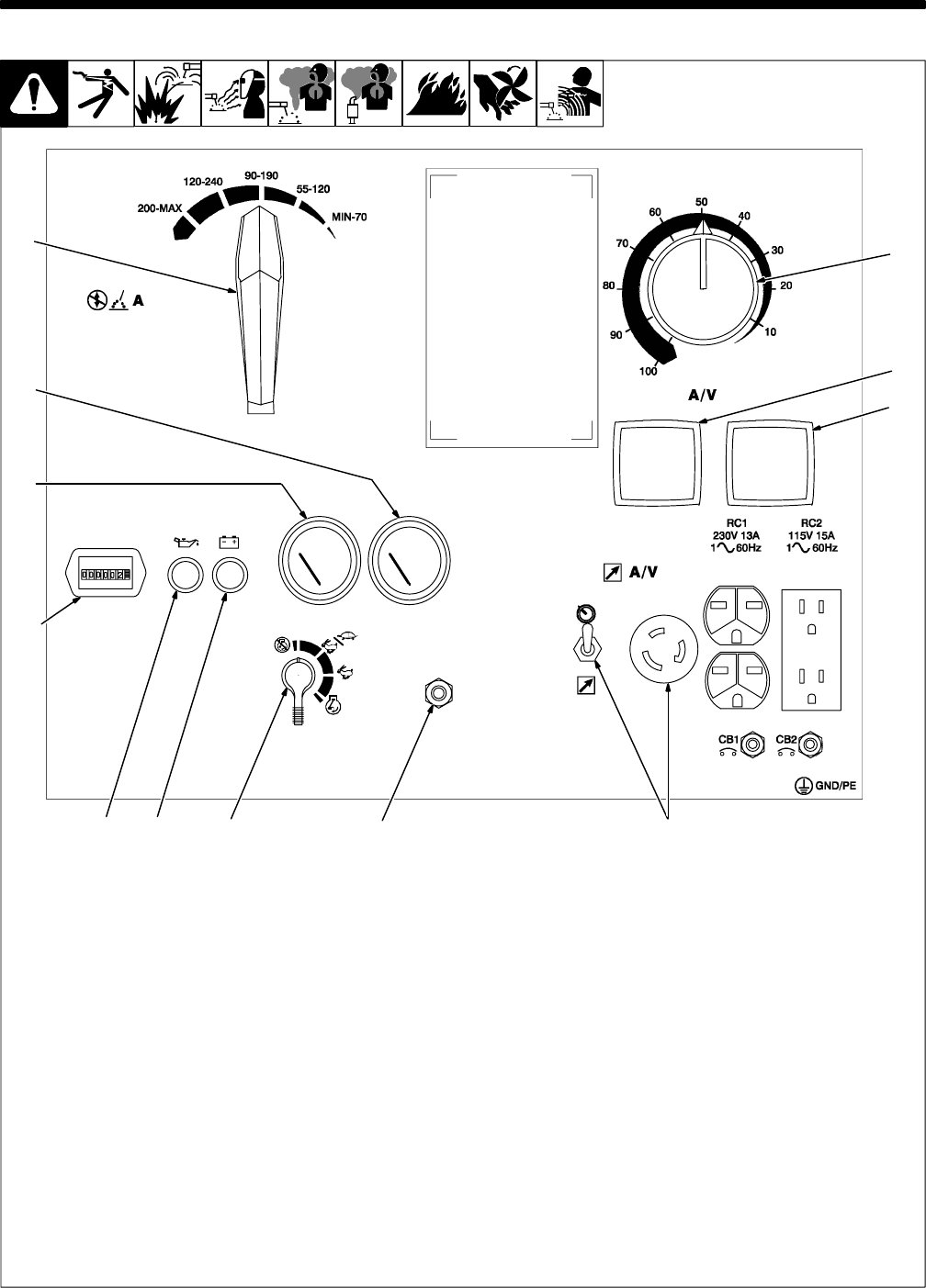
5-1. Front Panel Controls
Ref. ST-188 449
. This unit has a max OCV control circuit
that resets the Amperage/Voltage Con-
trol to maximum when the arc breaks.
When an arc is struck, weld output con-
trol returns to the front panel or remote
control setting. The Amperage/Voltage
Control adjusts amperage only when
welding and does not adjust open-circuit
voltage.
1 Ampere Range Switch
Y Do not switch under load.
2 Amperage/Voltage Control
Control adjusts amperage within range se-
lected by Ampere Range switch.
Weld output would be 140 A DC with controls
set as shown (50% of 90 to 190 A).
3 DC Voltmeter (Optional)
4 DC Ammeter (Optional)
5 Remote A/V Switch And Receptacle
(See Section 5-3)
6 Magnetic Shutdown Switch (Optional)
Use switch during start-up to bypass option-
al engine shutdown system. System stops
engine if oil pressure is too low or oil temper-
ature is too high.
7 Engine Control Switch
To Start: turn switch to Start while pressing
Shutdown switch. Release switches when
engine starts.
. If the engine does not start, let engine
come to a complete stop before attempt-
ing restart.
In Run position, engine runs at weld/power
speed. In Run/Idle position (optional), engine
runs at idle speed at no load and weld speed
with load applied.
To Stop: turn switch to Off position.
8 Battery Charging Warning Light
Light goes on when battery is not charging.
9 Oil Pressure Warning Light
Light goes on if oil pressure is too low. Light
also goes on if oil temperature is too high (if
unit has automatic shutdown option).
Y Stop engine and fix trouble if either
light goes on.
10 Engine Hour Meter
11 Oil Temperature Gauge/Switch
(Optional)
12 Oil Pressure Gauge/Switch (Optional)
1
2
11
12
5
3
4
67
10
89