


OM-173 413 Page 33
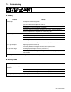
7-8. Troubleshooting
A. Welding
Trouble Remedy
No weld output. Check position of Ampere Range switch.
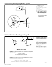
Place A/V control switch in Panel position, or place switch in Remote position and connect remote amper-
age control to Remote A/V receptacle (see Section 5-3).
Check and secure connections to Remote A/V receptacle.
Have Factory Authorized Service Agent check brushes and slip rings, and field excitation circuit.
Disconnect equipment from ac receptacles RC1 and RC2 during start-up.
Erratic weld output. Use dry, properly stored electrode.
Be sure connection to work piece is clean and tight.
Remove excessive coils from weld cables.
Check and tighten connections both inside and outside unit.
Have Factory Authorized Service Agent check brushes and slip rings, and field excitation circuit.
Low or high weld output. Adjust engine speed (see Section 7-5).
Have Factory Authorized Service Agent check field current regulator board PC1.
Low open-circuit voltage.
Check engine speed, and adjust if necessary (see Section 7-5).
Have Factory Authorized Service Agent check integrated rectifier SR2, Amperage/Voltage control R1,
and resistor R2.
Maximum weld output only in each
ampere range.
Have Factory Authorized Service Agent check Amperage/Voltage control R1, capacitor C8, diode D8,
integrated rectifier SR4, and control relay CR2.
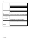
B. Auxiliary Power
Trouble Remedy
No output at auxiliary power
receptacles.
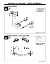
Reset circuit breaker CB1 and/or CB2 (see Section 6-1 or 6-2).
Disconnect equipment from ac receptacles RC1 and RC2 during start-up.
Have Factory Authorized Service Agent check brushes and slip rings, and field excitation circuit.
Low or high output at auxiliary power
receptacles.
Adjust engine speed (see Section 7-5).